Installation instructions (continued) p/n: as-1002 – S&B Filters Cold Air Intake Scoop AS-1002 User Manual
Page 3
15461 Slover Ave., Fontana, CA 92337 - Phone: (909) 947-0015 - Fax: (909) 947-0603 -
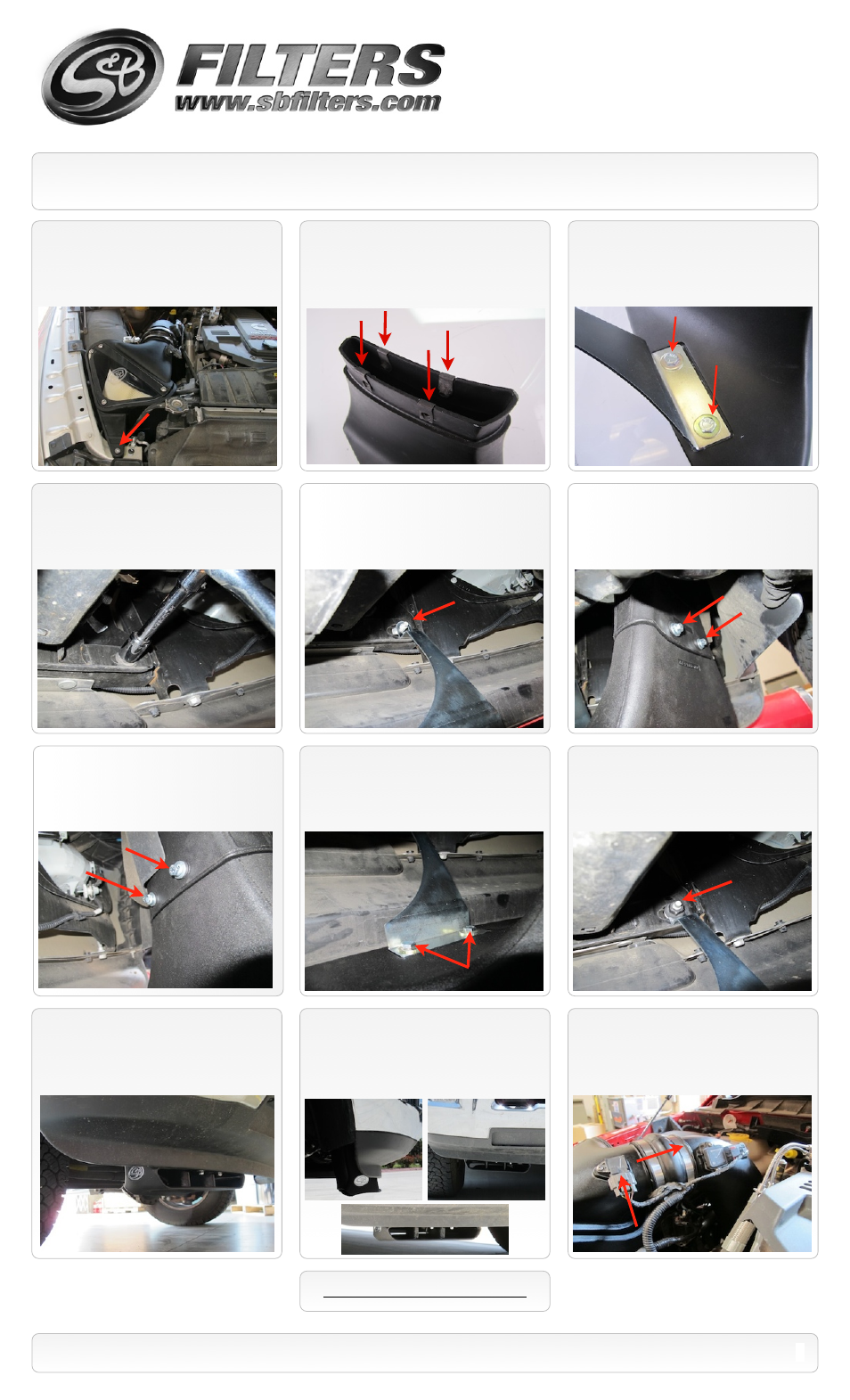
INSTALLATION INSTRUCTIONS (continued)
P/N: AS-1002
12.
Install the Mounting bracket
(H)
to the
top of the Scoop Base
(E)
using two 5/16”-18
Hex Bolts
(G)
, two 5/16” Hex Nuts
(H)
, and
four Flat Washers
(F)
.
Leave hand tight for
now.
18.
Reinstall the nut behind the front bumper
securing the Mounting bracket
(H)
. Torque to
factory specs.
19.
Check to make sure the Scoop
assembly does not interfere with the wheel or
wheel well liner. Turn the wheel in both
directions while trying to simulate full
suspension travel.
17.
When you are satisfied with the
positioning, tighten down the Mounting
bracket
(H)
to the Scoop Base
(E)
using two
1/2” wrenches (one on top and one inside).
20.
Inspect the entire installation, be sure
the kit is properly positioned and all fasteners
are secure.
SEE EXPLODED VIEW ON PAGE 5
3
11.
Install the four supplied Speed Clip Nuts
(C)
over the flange of the Scoop Base
(E)
.
Make sure the outside tabs snap into the
holes.
13.
From under the truck using 18mm
socket, remove the nut behind the bumper.
14.
Slide the Scoop base assembly up into
the Scoop Channel
(D)
and slide the
mounting bracket
(H)
over the stud behind the
bumper.
10.
Reinstall the Socket pan head screw
removed in Step #4.
15.
On the backside of the assembly,
secure the Scoop Base to the Channel using
the two 1/4”-20 Screws
(B)
, 1/4” Split Lock
washers
(K)
, and 1/4” Flat Washers
(A)
.
16.
On the frontside of the assembly,
secure the Scoop Base to the Channel using
the two 1/4”-20 Screws
(B)
, 1/4” Split Lock
washers
(K)
, and 1/4” Flat Washers
(A)
.
21.
Reinstall IAT sensor connection and
hump adapter. Tighten both #72 hose clamps.
Reconnect both batteries terminals. The
installation is now complete.
See warnings on Page #1.