S&B Filters Cold Air Intake Kit - Cotton Filter 75-5037 User Manual
Installation instructions, 6l duramax diesel “lb7
6/13/2008
REV-D
INSTALLATION INSTRUCTIONS
INSTALLATION INSTRUCTIONS
(OVER)
P/N
: 75-5037 / 75-5037D
2001-2004 Chevrolet
Silverado 2500 & 3500
2001-2004 GMC
Sierra 2500 & 3500
6.6L Duramax Diesel “LB7”
PARTS LIST
QTY DESCRIPTION
QTY DESCRIPTION
1
(Q) Intake Tube
1
(F) # 80 Hose Clamp
1
(D) Air Box
1
(M) # 72 Hose Clamp
1
(K) Air Box Adapter
2
(N) # 64 Hose Clamp
1
(C) Air Filter
2
(J) 5/16-18 SS Screw
1
(L) Hump Adapter
1
(E) Clear Lid
1
(O) Step Adapter
4
(B) SS Concave Washer
1
(H) MAF Gasket
4
(A) SS 10/24 Phillips Screw
2
(I) M4 MAF Screw
1
(P) # 60 Hose Clamp
2
(G) M4 Rubber Washer
4
(R) M6 Allen Head Screw
4
(S) 3/8”x1” SS Washer
TOOLS REQUIRED
10 mm Wrench & Socket
12mm Socket
5/16” Nut driver or
Flat Blade Screwdriver
Phillips Screwdriver
T-20 Torx Wrench (supplied)
Your S&B Air Filter P/N
KF-1035 is factory oiled
and ready to use.
When serviced it will
require 87g (main body)
plus 17g (top) of S&B
Filter Oil.
4mm Allen Wrench
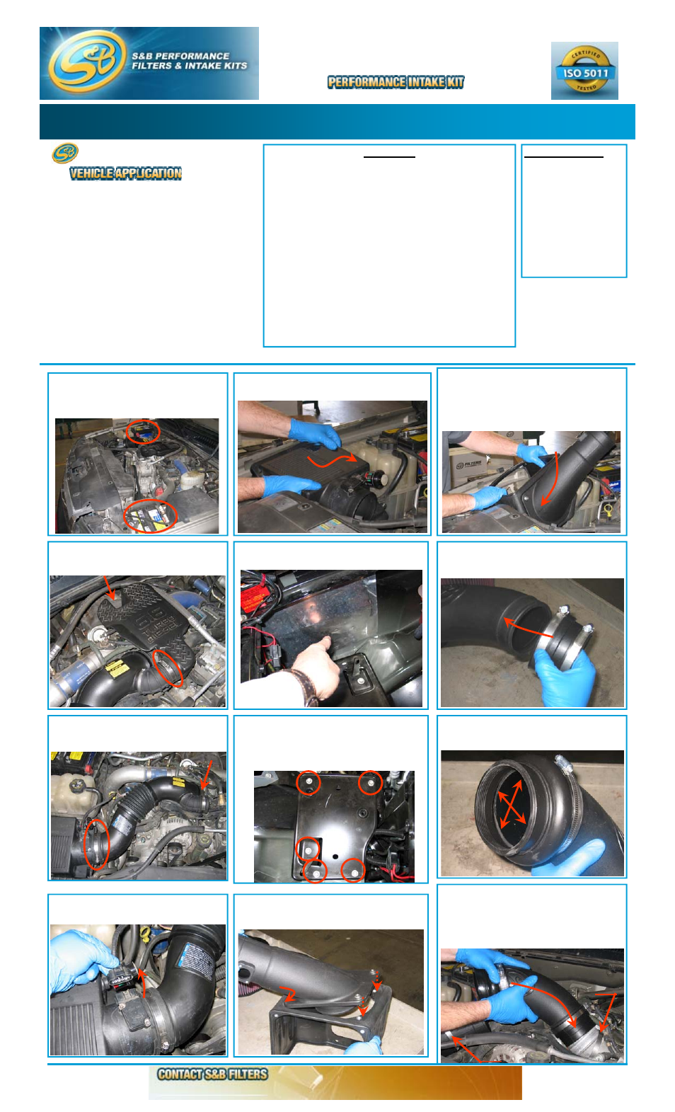
1.
With the ignition switched off, place
vehicle in Park and or set Parking Brake.
Then disconnect both negative battery
cables.
2.
Loosen the bolt and the hose clamp that
secure the OE resonator chamber and re-
move the chamber from the intake tube.
3.
Loosen the hose clamps at the OE air
box and at the turbo inlet, then remove the
OE intake tube.
4.
Disconnect the MAF sensor electrical
connection.
5.
Lift up and pull towards the engine to remove
the OE air box from the vehicle.
7.
Remove the OE air box tray. If long enough,
you may use four of these bolts to secure the
S&B Air Box (D) to the vehicle. If not use the
supplied M6 allen head screws (R) and SS
washers (S).
6.
Remove the OE foil from the inner fender,
this will allow cooler air to enter the S&B air box.
8.
Attach the S&B Filter Adapter (K) to the S&B
Air box (D), secure using the 5/16 screws (J)
provided.
9.
Place the S&B Air Box assembly into the
vehicle, align the 4 holes with the OE mounting
locations and secure using either the OE bolts
or the supplied hardware. You may need to
loosen these bolts to align the tubes during
step # 12, then retighten.
10.
Slide the Step Adapter (O) over the small
end of the S&B Intake Tube (Q) and secure
the # 64 Hose Clamp (N).
11.
Slide the large side of the Hump Adapter
(L) over the large end of the S&B Intake Tube
(Q) until the small side hits the end of the tube.
12.
Place the # 60 Hose Clamp (P) over the
turbo inlet and a # 64 Hose Clamp (M) over the
filter adapter (K). Then slip the S&B Intake
Tube assembly over the turbo inlet, align the
large end to the filter adapter then secure the
# 60 hose clamp (P).
∗
Kit may not fit vehicles with the following
Aftermarket Parts installed.
∗
Body Lift
∗
Custom Hood
∗
Turbo Upgrade
∗
Intercooler Upgrades
(909) 947-0015 Phone (909) 947-0603 FAX
www.sbfilters.com
#60
#64