Peerless-AV GC-UNV - Installation User Manual
Page 8
Visit the Peerless Web Site at www.peerlessmounts.com
For customer care call 1-800-865-2112 or 708-865-8870.
8 of 13
ISSUED: 01-28-11 SHEET #:125-9176-1
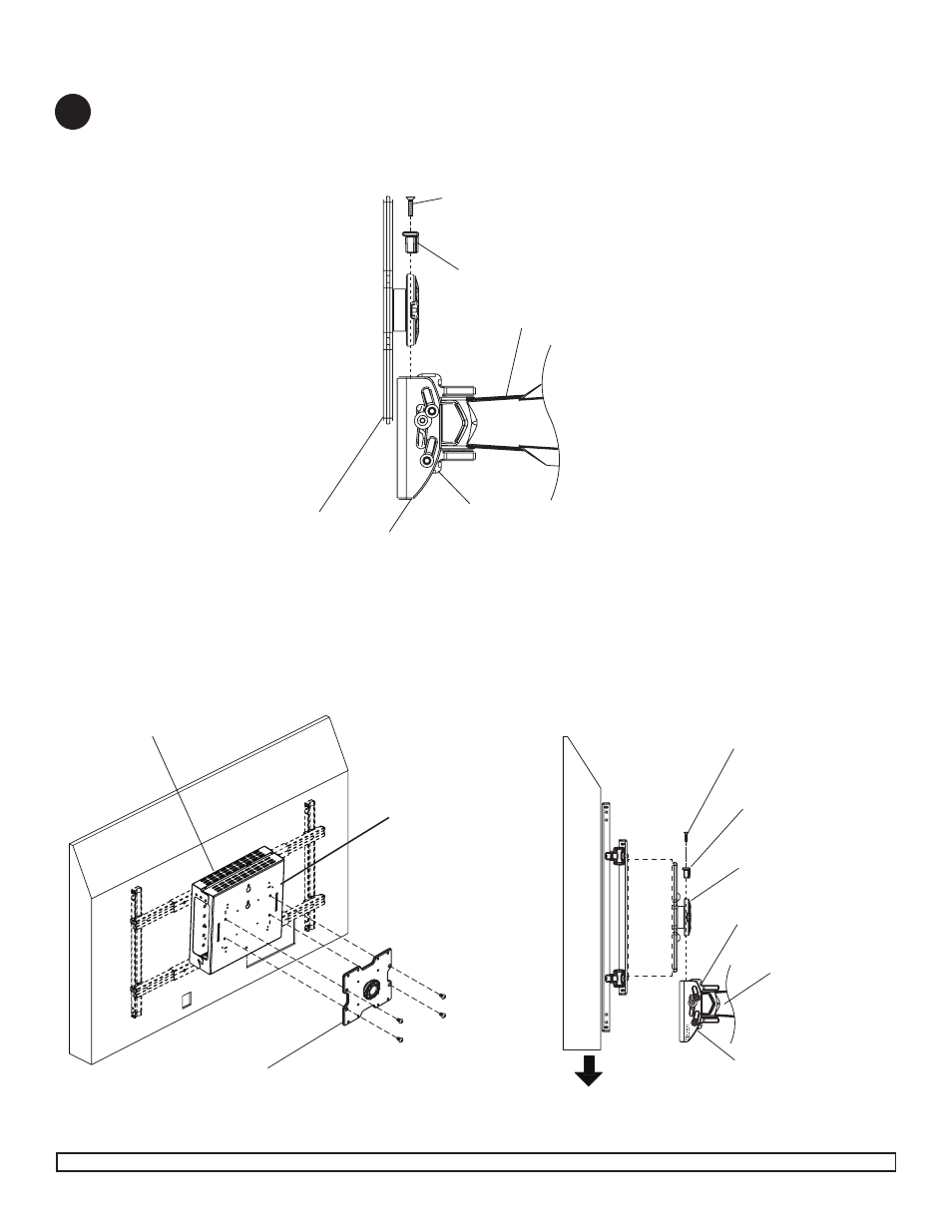
Remove two M5 x 20 mm screws from the rollbrake. Lift adapter plate of wall arm mount out from tilt bracket as
shown.
NOTE: M5 X 25 mm screw may need to be loosened a few turns to allow adapter bracket to be removed using 4
mm allen wrench (N).
Secure adapter plate of wall arm mount to wall plate (
A) with
four M10 x 15 mm penta-pin screws (
E) using M10 penta-pin
tool (
F) as shown below.
Insert the puck of adapter plate into the tilt
bracket slot as shown. Attach brake pad assembly so
that the brake pad is snug against the adapter plate.
Adjust roll position of adapter plate to level screen then
lock puck in place by tightening M5 x 25 mm screw on
the underside of tilt bracket.
Tighten all (M5 x 20 mm, M5 x 25 mm) screws.
Attaching Adapter Plate to SA745PU, SA750PU, SA760PU, SA770PU
5
ADAPTER PLATE
B
E
M5 X 20 MM SCREW
ROLL BRAKE
ADAPTER PLATE
WALL ARM MOUNT
M5 X 25 MM SCREW
TILT BRACKET
M5 X 20 MM SCREW
ROLL BRAKE
ADAPTER PLATE
M5 X 25 MM SCREW
TILT BRACKET
WALL ARM MOUNT
A