Peerless-AV GC-UNV - Installation User Manual
Page 11
Visit the Peerless Web Site at www.peerlessmounts.com
For customer care call 1-800-865-2112 or 708-865-8870.
11 of 13
ISSUED: 01-28-11 SHEET #:125-9176-1
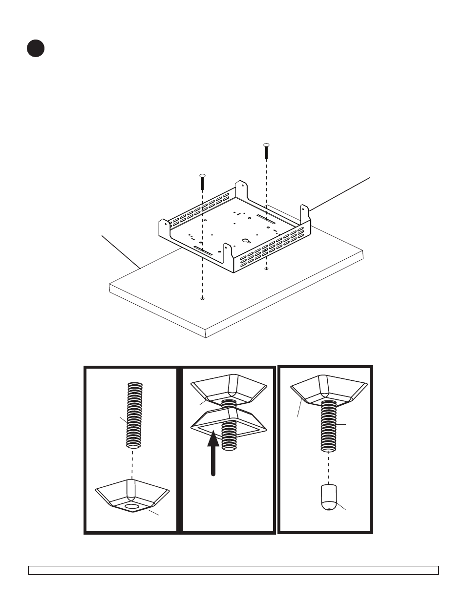
Figure. 4.1
Figure. 4.2
Figure. 4.3
BOTTOM OF MOUNTING SURFACE
TOP OF MOUNTING SURFACE
Mounting Surface Lock down Installation
4
Place wall plate (
B) onto mounting surface as a template. Level, and mark the center of two rectangular mounting
holes. Drill two 5/16” (8 mm) dia. holes through mounting surface. Secure using two carriage bolts (
R) through wall
plate (
B) and mounting surface as shown in figure 4.1.
Hand tighten slope nut (
S) through 1/4-20 x 1 3/4" carriage bolt (R) until snug against bottom of desktop surface as
shown in figure 4.2.
Thread another slope nut (
S) upside-down, about two turns from first slope nut (S). Insert a open box wrench
between both slope nuts (
S) and tighten. NOTE: Avoid jamming both slope nuts (S) together, doing so may make it
difficult to remove slope nut used for tightening first slope nut (
S) as shown in figure 4.3.
After slope nut is secure remove bottom slope nut and add plastic cap (
T) as shown in figure 4.4.
Repeat with remaining 1/4-20 x 1 3/4" carriage bolt (
R).
B
Figure. 4.4
TIGHTENING
SLOPE NUT
R
S
R
S
R
S
T