Rainbow Electronics MAX3646 User Manual
Page 2
MAX3646
155Mbps to 622Mbps SFF/SFP
Laser Driver with Extinction Ratio Control
2
_______________________________________________________________________________________
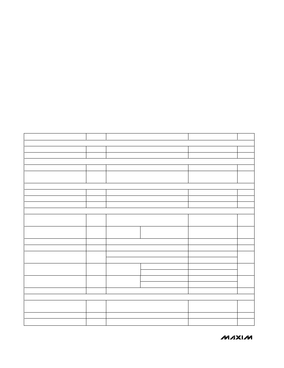
ABSOLUTE MAXIMUM RATINGS
ELECTRICAL CHARACTERISTICS
(V
CC
= +2.97V to +3.63V, T
A
= -40°C to +85°C. Typical values are at V
CC
= +3.3V, I
BIAS
= 60mA, I
MOD
= 60mA, T
A
= +25°C, unless
otherwise noted.) (Notes 1, 2)
Stresses beyond those listed under “Absolute Maximum Ratings” may cause permanent damage to the device. These are stress ratings only, and functional
operation of the device at these or any other conditions beyond those indicated in the operational sections of the specifications is not implied. Exposure to
absolute maximum rating conditions for extended periods may affect device reliability.
Supply Voltage V
CC
...............................................-0.5V to +6.0V
IN+, IN-, TX_DISABLE, TX_FAULT, SHUTDOWN,
BC_MON, PC_MON, APCFILT1, APCFILT2,
MD, TH_TEMP, MODTCOMP, MODBCOMP,
MODSET, and APCSET Voltage.............-0.5V to (V
CC
+ 0.5V)
OUT+, OUT-, BIAS Current.............................-20mA to +150mA
Continuous Power Dissipation (T
A
= +85°C)
24-Pin QFN (derate 20.8mW/°C above +85°C) .........1805mW
Operating Junction Temperature Range ...........-55°C to +150°C
Storage Temperature Range .............................-55°C to +150°C
PARAMETER
SYMBOL
CONDITIONS
MIN
TYP
MAX
UNITS
POWER SUPPLY
Supply Current
I
CC
(Note 3)
47
60
mA
Power-Supply Noise Rejection
PSNR
f
≤
1MHz, 100mA
P-P
(Note 4)
33
dB
I/O SPECIFICATIONS
Differential Input Swing
V
ID
DC-coupled, Figure 1
0.2
2.4
V
P-P
Common-Mode Input
V
CM
1.7
V
CC
-
V
ID
/ 4
V
LASER BIAS
Bias-Current-Setting Range
1
100
mA
Bias Off Current
TX_DISABLE = high
0.1
mA
Bias-Current Monitor Ratio
I
BIAS
/ I
BC_MON
68
79
95
mA/mA
LASER MODULATION
Modulation Current-Setting
Range
I
MOD
(Note 5)
5
85
mA
Output Edge Speed
20% to 80%
(Notes 6, 7)
5mA
≤
I
MOD
≤
85mA
100
200
ps
Output Overshoot/Undershoot
(Note 7) (with 2pF between OUT+ and OUT-)
±
6
%
Random Jitter
(Notes 6, 7)
1.1
2.5
ps
RMS
622Mbps, 5mA
≤
I
MOD
≤
85mA
24
46
Deterministic Jitter (Notes 6, 8)
155Mbps, 5mA
≤
I
MOD
≤
85mA
45
100
ps
P-P
5mA
≤
I
MOD
≤
10mA
±175
±600
Modulation-Current Temperature
Stability
(Note 6)
10mA < I
MOD
≤
85mA
±125
±480
ppm/
°
C
5mA
≤
I
MOD
≤
10mA
±
20
Modulation-Current-Setting Error
15
Ω
load,
T
A
= +25
°
C
10mA < I
MOD
≤
85mA
±
15
%
Modulation Off Current
TX_DISABLE = high
0.1
mA
AUTOMATIC POWER AND EXTINCTION RATIO CONTROLS
Monitor-Diode Input Current
Range
I
MD
Average current into the MD pin
18
1500
µA
MD Pin Voltage
1.4
V
MD Current Monitor Ratio
I
MD
/ I
PC_MON
0.85
0.93
1.15
mA/mA