Max3301e usb on-the-go transceiver and charge pump – Rainbow Electronics MAX3301E User Manual
Page 26
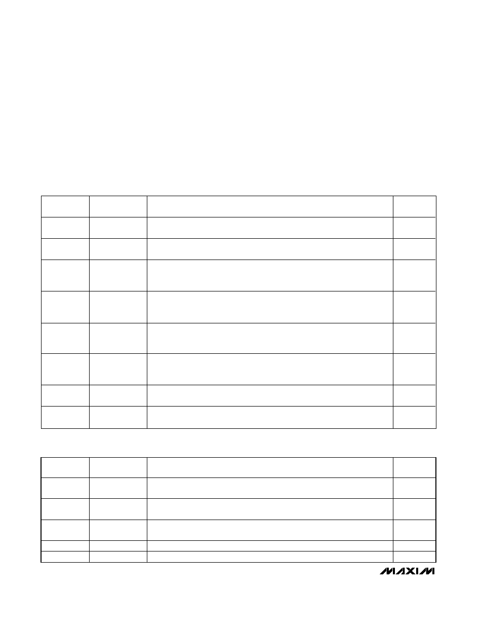
Special-Function Registers
Tables 14 and 15 describe the special-function regis-
ters. Special-function register 1 determines whether
hardware or software controls the maximum data rate
and suspend behavior, sets the direction of data trans-
fer, and toggles general-purpose buffer mode. Special-
function register 2 enables shutdown mode, configures
the interrupt output as open-drain or push-pull, sets the
TRM power source, and controls the D+/D- connections
for audio mode. The special-function registers have two
addresses that implement write-one-set and write-one-
clear features for each of these registers. Writing a one
to the set address sets that bit to one. Writing a one to
the clear address resets that bit to zero. Writing a zero
to either address has no effect on the bits.
MAX3301E
USB On-the-Go Transceiver and Charge Pump
26
______________________________________________________________________________________
BIT NUMBER
SYMBOL
CONTENTS
VALUE AT
POWER-UP
0
int_sdwn
S et to 0 for nor m al op er ati on. S et to 1 to enter i nter r up t shutd ow n m od e. The I
2
C
i nter face and i nter r up t sour ces r em ai n acti ve, w hi l e al l other ci r cui tr y i s off.
0
1
spd_susp_ctl
S et to 0 to contr ol the M AX 3301E b ehavi or w i th S P D and S U S . S et to 1 to contr ol the
M AX 3301E b ehavi or w i th the sp eed and susp end b i ts i n contr ol r eg i ster 1 ( see Tab l e 7) .
0
2
bi_di
Set to 0 to transfer data from DAT_VP and SE0_VM to D+ and D-, respectively.
DAT_VP and SE0_VM are always inputs when this bit is 0. Set to 1 to control the
direction of data transfer with OE/INT.
1
3
dminus_dir
Set to 0 to transfer data from SE0_VM to D-. Set to 1 to transfer data from D- to
SE0_VM. Ensure that gp_en = 1, dat_se0 = 1, uart_en = 0, and OE/INT = low to
activate this function.
0
4
dplus_dir
Set to 0 to transfer data from DAT_VP to D+. Set to 1 to transfer data from D+ to
DAT_VP. Ensure that gp_en = 1, dat_se0 = 1, uart_en = 0, and OE/INT = low to
activate this function.
0
5
int_source
Set to 0 to use cr_int as the interrupt source for bit 7 of the interrupt source
register. Set to 1 to use sess_end as the interrupt source for bit 7 of the interrupt
source register (see Table 10).
0
6
sess_end
Session end comparator status (read only). Sess_end = 0 when V
BUS
>
sess_end threshold. Sess_end = 1 when V
BUS
< sess_end threshold.
7
gp_en
Set to 0 to disable general-purpose buffer mode. Set to 1 to enable general-
purpose buffer mode.
0
Table 14. Special-Function Register 1 (Write to Address 12h to Set, Write to Address 13h
to Clear)
BIT NUMBER
SYMBOL
CONTENTS
VALUE AT
POWER-UP
0
sdwn
Set to 0 for normal operation. Set to 1 to enable shutdown mode. Only the I
2
C
interface remains active in shutdown.
1
1
irq_mode
Set to 0 to set INT and OE/INT as open-drain outputs. Set to 1 to set INT and
OE/INT as push-pull outputs.
0
2
xcvr_input_disc
S et to 0 to l eave the D+ /D - si ng l e-end ed r ecei ver inp uts connected . S et to 1 to
d i sconnect the D + /D- r ecei ver inp uts to r educe p ow er consump ti on i n audi o mod e.
0
3
reg_sel
Set to 0 to power TRM from V
CC
. Set to 1 to power TRM from V
BUS
.
0
4, 5, 6, 7
—
Reserved. Set to 0 for normal operation.
0000
Table 15. Special-Function Register 2 (Write to Address 16h to Set, Write to Address 17h
to Clear)