Max3301e usb on-the-go transceiver and charge pump, Table 6. register map – Rainbow Electronics MAX3301E User Manual
Page 22
MAX3301E
USB On-the-Go Transceiver and Charge Pump
22
______________________________________________________________________________________
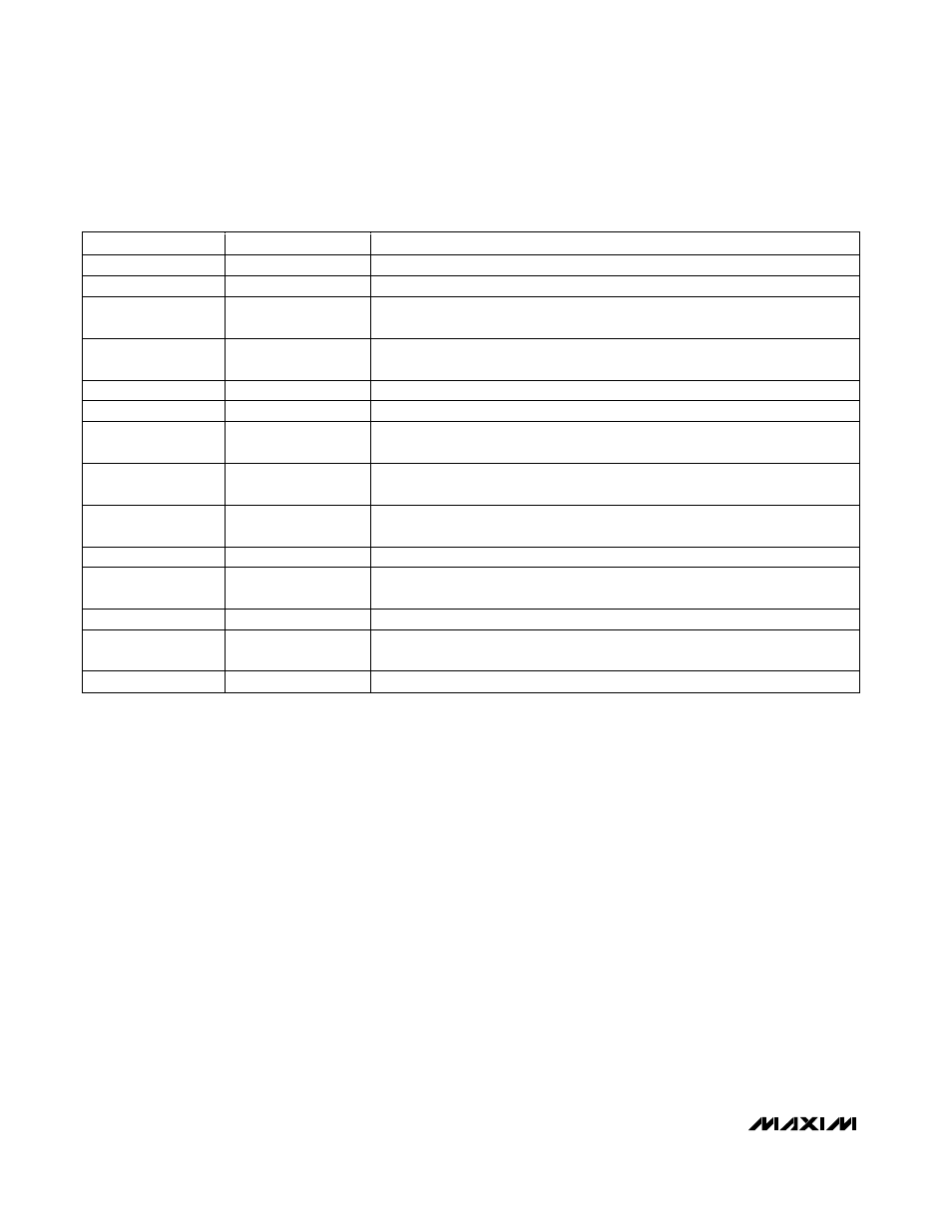
REGISTER
MEMORY ADDRESS
DESCRIPTION
Vendor ID
00h, 01h
Read only. The contents of registers 00h and 01h are 6Ah and 0Bh, respectively.
Product ID
02h, 03h
Read only. The contents of registers 02h and 03h are 01h and 33h, respectively.
Control 1
04h (set)
05h (clear)
Sets operating modes, maximum data rate, and direction of data transfer.
Control 2
06h (set)
07h (clear)
Controls D+/D- pullup/pulldown resistor connections, ID_IN state, and V
BUS
behavior.
Interrupt source
08h (read)
Read only.
Unused*
09h
Not used.
Interrupt latch
0Ah (set)
0Bh (clear)
Indicates which interrupts have occurred.
Interrupt-enable
Falling edge
0Ch (set)
0Dh (clear)
Enables interrupts for high-to-low transitions.
Interrupt-enable
Rising edge
0Eh (set)
0Fh (clear)
Enables interrupts for low-to-high transitions.
Unused*
10h, 11h
Not used.
Special function 1
12h (set)
13h (clear)
Enables hardware/software control of the MAX3301E's is behavior, controls
interrupt activity, and controls operating modes.
Revision ID
14h, 15h
Read only. The contents of registers 14h and 15h are 77h and 41h, respectively.
Special function 2
16h (set)
17h (clear)
Sets operating modes, INT output configuration, D+/D- behavior in audio mode,
and TRM source.
Unused*
18h–Fh
Not used.
Table 6. Register Map
Registers
Control Registers
There are two read/write control registers. Control regis-
ter 1 (Table 7) sets operating modes, sets the data rate,
and controls the direction of data transfer. Control regis-
ter 2 (Table 8) connects the D+/D- pullup or pulldown
resistors, sets the V
BUS
charge/discharge conditions,
and grounds ID_IN. The control registers have two
addresses that implement write-one-set and write-one-
clear features for each of these registers. Writing a one
to the set address sets that bit to one. Writing a one to
the clear address resets that bit to zero. Writing a zero
to either address has no effect on the bits.
Interrupt Registers
Four registers control all interrupt behavior of the
MAX3301E. A source register (Table 10) indicates the
current status of the various interrupt sources. An inter-
rupt latch register (Table 11) indicates which interrupts
have occurred. An interrupt-enable low and interrupt-
enable high register enable interrupts on rising or falling
(or both) transitions. Tables 10–13 provide the bit con-
figurations for the various interrupt registers. The inter-
rupt latch, interrupt-enable low, and interrupt-enable
high registers have two addresses that implement write-
one-set and write-one-clear features for each of these
registers. Writing a one to the set address sets that bit to
one. Writing a one to the clear address resets that bit to
zero. Writing a zero to either address has no effect on
the bits.
*When writing to an unused register, the device generates a NACK and the register index does not increment.