Max3301e usb on-the-go transceiver and charge pump – Rainbow Electronics MAX3301E User Manual
Page 20
MAX3301E
USB On-the-Go Transceiver and Charge Pump
20
______________________________________________________________________________________
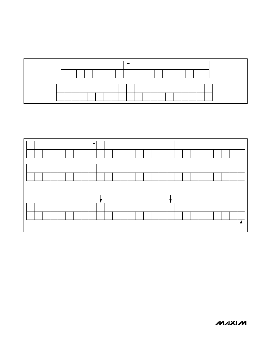
the master to send the next data byte. The MAX3301E
sends an acknowledge bit after each data byte. If an
unsupported register is selected, the MAX3301E sends
a NACK to the master and the register index does not
increment (see Figure 20).
Burst-Mode Read Byte Format
The MAX3301E allows a master device to read data
from sequential registers with the burst-mode read byte
protocol (see Figure 21). The master device first sends
the slave address, followed by a zero. The MAX3301E
then sends an acknowledge bit. Next, the master sends
the register address to the MAX3301E, which then gen-
erates another acknowledge bit. The master then sends
a stop (P) condition to the MAX3301E. Next, the master
sends a start condition, followed by the MAX3301E’s
slave address, and then a one to indicate a read com-
mand. The MAX3301E then sends data to the master
device, one byte at a time. The master sends an
acknowledge bit to the MAX3301E after each data byte,
and the register address of the MAX3301E increments
after each byte. This continues until the master sends a
stop (P) condition. If an unsupported register address is
encountered, the MAX3301E sends a byte of zeros.
S
SLAVE ADDRESS
(7 BITS)
A6
A5
A4
A3
A2
A1
A0
0
A
REGISTER ADDRESS (K)
(8 BITS)
MSB
LSB
A
A
MSB
LSB
DATA (K)
(8 BITS)
DATA (K+1)
(8 BITS)
A
DATA (K+2)
(8 BITS)
MSB
LSB
A
A
MSB
LSB
DATA (K+N)
(8 BITS)
MSB
LSB
P
S
SLAVE ADDRESS
(7 BITS)
A6
A5
A4
A3
A2
A1
A0
0
A
UNSUPPORTED REGISTER ADDRESS (K)
(8 BITS)
MSB
LSB
A
NA
MSB
LSB
DATA (K)
(8 BITS)
MAX3301E RECOGNIZES
ITS ADDRESS
MAX3301E SENDS
AN ACK
MAX3301E RECOGNIZES A WRITE TO AN
UNSUPPORTED LOCATION, THEN SENDS A NACK
R/W
R/W
Figure 20. Burst-Mode Write Byte Format
S
SLAVE ADDRESS
(7 BITS)
A6
A5
A4
A3
A2
A1
A0
0
0
0
A
REGISTER ADDRESS
(8 BITS)
MSB
LSB
A
RS
SLAVE ADDRESS
(7 BITS)
A6
A5
A4
A3
A2
A1
A0
1
1
0
0
A
DATA
(8 BITS)
MSB
LSB
NA
P
R/W
R/W
Figure 19. Read Byte Format
R/W: Read/write (R/W = 1: read; R/W = 0: write)
S: Start condition
RS: Repeated start condition
P: Stop condition
A: Acknowledge bit from the slave
NA: Not-acknowledged bit from the master
Blank: Master transmission