Rainbow Electronics AT89LP216 User Manual
Page 69
69
3621A–MICRO–6/06
AT89LP216 [Preliminary]
Notes:
1. Program Enable must be the first command issued after entering into programming mode.
2. Any number of Data bytes from 1 to 32 may be written/read. The internal address is incremented between each byte.
3. Each byte address selects one fuse or lock bit. Data bytes must be 00h or FFh.
for Fuse definitions.
for Lock Bit definitions.
6. Atmel Signature Bytes:
7. Symbol Key:
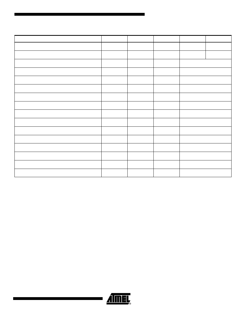
Table 23-2.
Programming Command Summary
Command
Opcode
Addr High
Addr Low
Data 0
Data n
Program Enable
1010 1100
0101 0011
–
–
–
Chip Erase
1000 1010
–
–
–
–
Read Status
0110 0000
xxxx xxxx
xxxx xxxx
Status Out
Load Page Buffer
0101 0001
xxxx xxxx
xxxb bbbb
DataIn 0 ... DataIn n
Write Code Page
0101 0000
xxxx xaaa
aaab bbbb
DataIn 0 ... DataIn n
Write Code Page with Auto-Erase
0111 0000
xxxx xaaa
aaab bbbb
DataIn 0 ... DataIn n
Read Code Page
0011 0000
xxxx xaaa
aaab bbbb
DataOut 0 ... DataOut n
Write User Fuses
1110 0001
0000 0000
000b bbbb
DataIn 0 ... DataIn n
Write User Fuses with Auto-Erase
1111 0001
0000 0000
000b bbbb
DataIn 0 ... DataIn n
Read User Fuses
0110 0001
0000 0000
000b bbbb
DataOut 0 ... DataOut n
Write Lock Bits
1110 0100
0000 0000
000b bbbb
DataIn 0 ... DataIn n
Read Lock Bits
0110 0100
0000 0000
000b bbbb
DataOut 0 ... DataOut n
Write User Signature Page
0101 0010
xxxx xxxx
xaab bbbb
DataIn 0 ... DataIn n
Write User Signature Page with Auto-Erase
0111 0010
xxxx xxxx
xaab bbbb
DataIn 0 ... DataIn n
Read User Signature Page
0011 0010
xxxx xxxx
xaab bbbb
DataOut 0 ... DataOut n
Read Atmel Signature Page
0011 1000
xxxx xxxx
xxxb bbbb
DataOut 0 ... DataOut n
AT89LP216:
Address
00H = 1EH
01H = 29H
02H = FFH
a:
Page Address Bit
b:
Byte Address Bit
x:
Don’t Care Bit