Rainbow Electronics AT89LP216 User Manual
Page 56
56
3621A–MICRO–6/06
AT89LP216 [Preliminary]
Note:
1. Debouncing modes require the use of Timer 1 to generate the sampling delay.
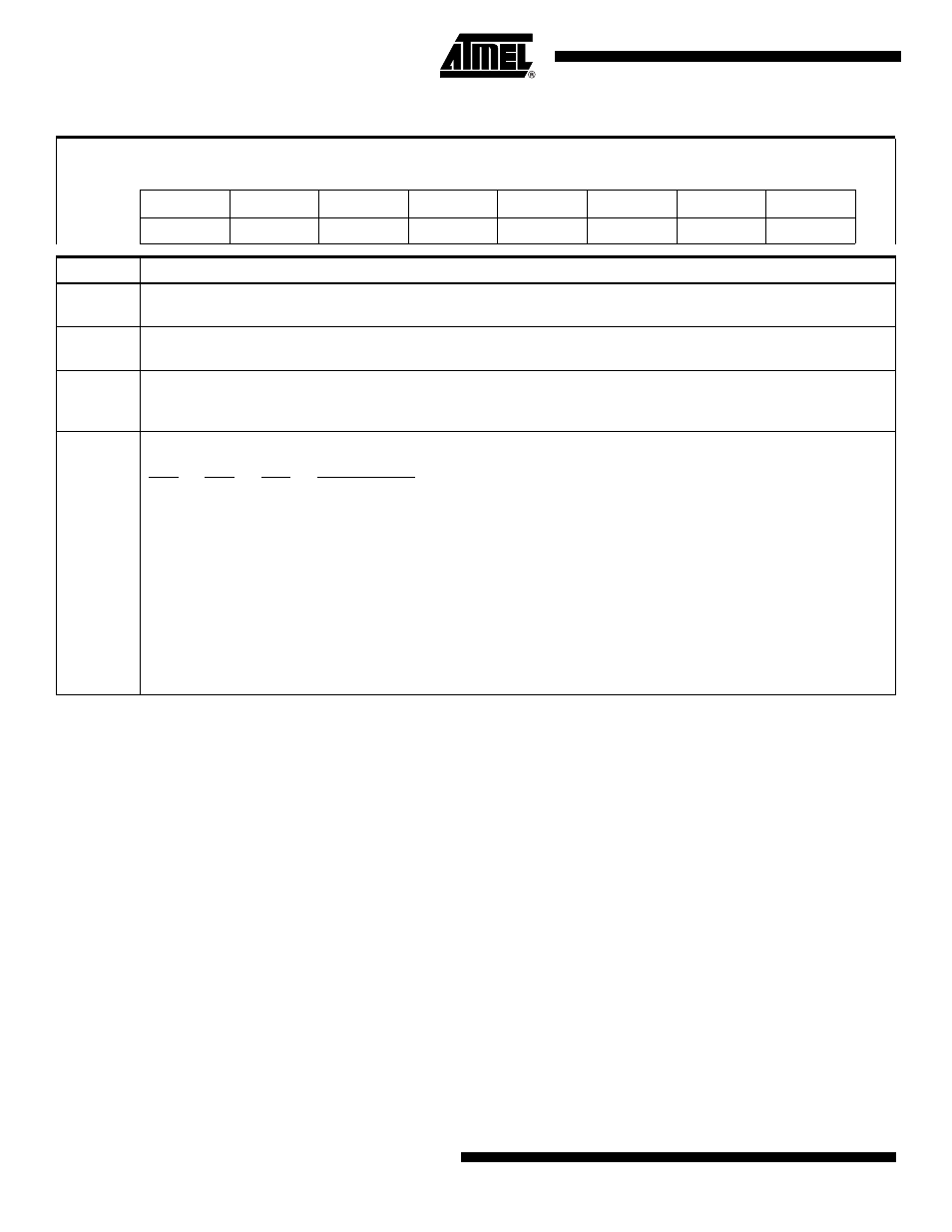
Table 19-1.
ACSR
– Analog Comparator Control & Status Register
ACSR = 97H
Reset Value = XXX0 0000B
Not Bit Addressable
–
–
CIDL
CF
CEN
CM3
CM1
CM0
Bit
7
6
5
4
3
2
1
0
Symbol
Function
CIDL
Comparator Idle Enable. If CIDL = 1 the comparator will continue to operate during Idle mode. If CIDL = 0 the
comparator is powered down during Idle mode. The comparator is always shut down during Power-down mode.
CF
Comparator Interrupt Flag. Set when the comparator output meets the conditions specified by the CM [2:0] bits and CEN
is set. The flag must be cleared by software. The interrupt may be enabled/disabled by setting/clearing bit 6 of IE.
CEN
Comparator Enable. Set this bit to enable the comparator. Clearing this bit will force the comparator output low and
prevent further events from setting CF. When CEN = 1 the analog input pins, P1.0 and P1.1, have their digital inputs
disabled.
CM [2:0]
Comparator Interrupt Mode
CM2
CM1
CM0
Interrupt Mode
0
0
0
Negative (Low) level
0
0
1
Positive edge
0
1
0
Toggle with debouncing
0
1
1
Positive edge with debouncing
1
0
0
Negative edge
1
0
1
Toggle
1
1
0
Negative edge with debouncing
1
1
1
Positive (High) level