Figure 13-3 – Rainbow Electronics AT89LP216 User Manual
Page 24
24
3621A–MICRO–6/06
AT89LP216 [Preliminary]
13.1.2
Input-only Mode
The input only port configuration is shown in
. The output drivers are tristated. The
input includes a Schmitt-triggered input for improved input noise rejection. The input circuitry of
P1.3, P3.2 and P3.3 is not disabled during Power-down (see
). Input pins can be
safely driven to 5.5V even when operating at lower V
CC
levels; however, the input threshold of
the Schmitt trigger will be set by the V
CC
level and must be taken into consideration.
Figure 13-2. Input Only
Figure 13-3. Input Only for P1.3, P3.2 and P3.3
13.1.3
Open-drain Output
The open-drain output configuration turns off all pull-ups and only drives the pull-down transistor
of the port pin when the port latch contains a logic “0”. To be used as a logic output, a port con-
figured in this manner must have an external pull-up, typically a resistor tied to V
CC
. The pull-
down for this mode is the same as for the quasi-bidirectional mode. The open-drain port configu-
ration is shown in
.The input circuitry of P1.3, P3.2 and P3.3 is not disabled during
Power-down (see
). Open-drain pins can be safely pulled high to 5.5V even when
operating at lower V
CC
levels; however, the input threshold of the Schmitt trigger will be set by
the V
CC
level and must be taken into consideration.
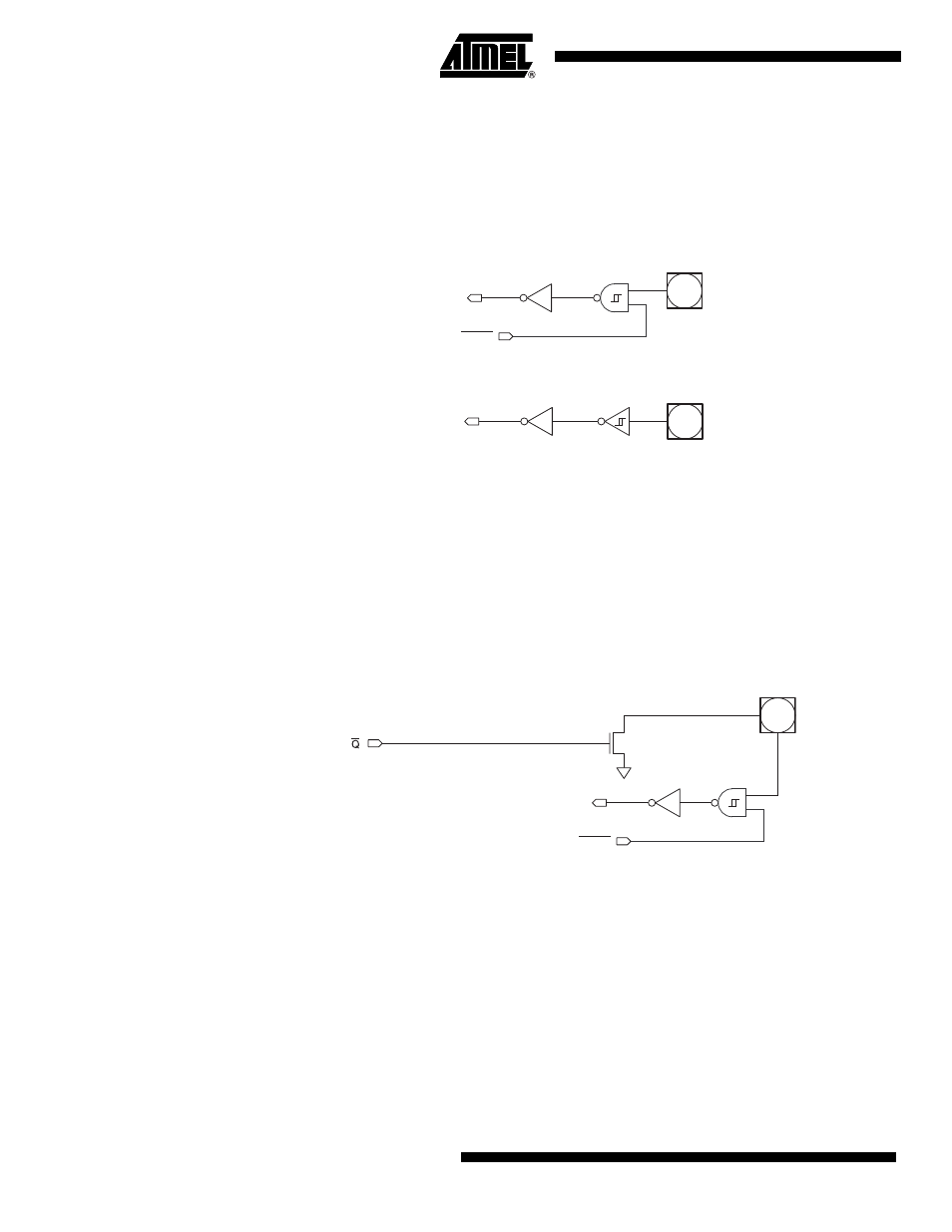
Figure 13-4. Open-Drain Output
13.1.4
Push-pull Output
The push-pull output configuration has the same pull-down structure as both the open-drain and
the quasi-bidirectional output modes, but provides a continuous strong pull-up when the port
latch contains a logic “1”. The push-pull mode may be used when more source current is needed
from a port output. The push-pull port configuration is shown in
. The input circuitry of
P1.3, P3.2 and P3.3 is not disabled during Power-down (see
Port
Pin
Input
Data
PWD
Port
Pin
Input
Data
Port
Pin
From Port
Register
Input
Data
PWD