2 mode 1 - 16-bit auto-reload timer/counter, 2 mode 1 – 16-bit auto-reload timer/counter – Rainbow Electronics AT89LP216 User Manual
Page 28
28
3621A–MICRO–6/06
AT89LP216 [Preliminary]
Figure 14-1. Timer/Counter 1 Mode 0: Variable Width Counter
Mode 0 operation is the same for Timer 0 as for Timer 1, except that TR0, TF0 and INT0 replace
the corresponding Timer 1 signals in
. There are two different GATE bits, one for
Timer 1 (TMOD.7) and one for Timer 0 (TMOD.3). The INT0 and INT1 pins are shared with the
XTAL oscillator. They may only be used for the GATE function when using the internal RC oscil-
lator as the system clock.
14.2
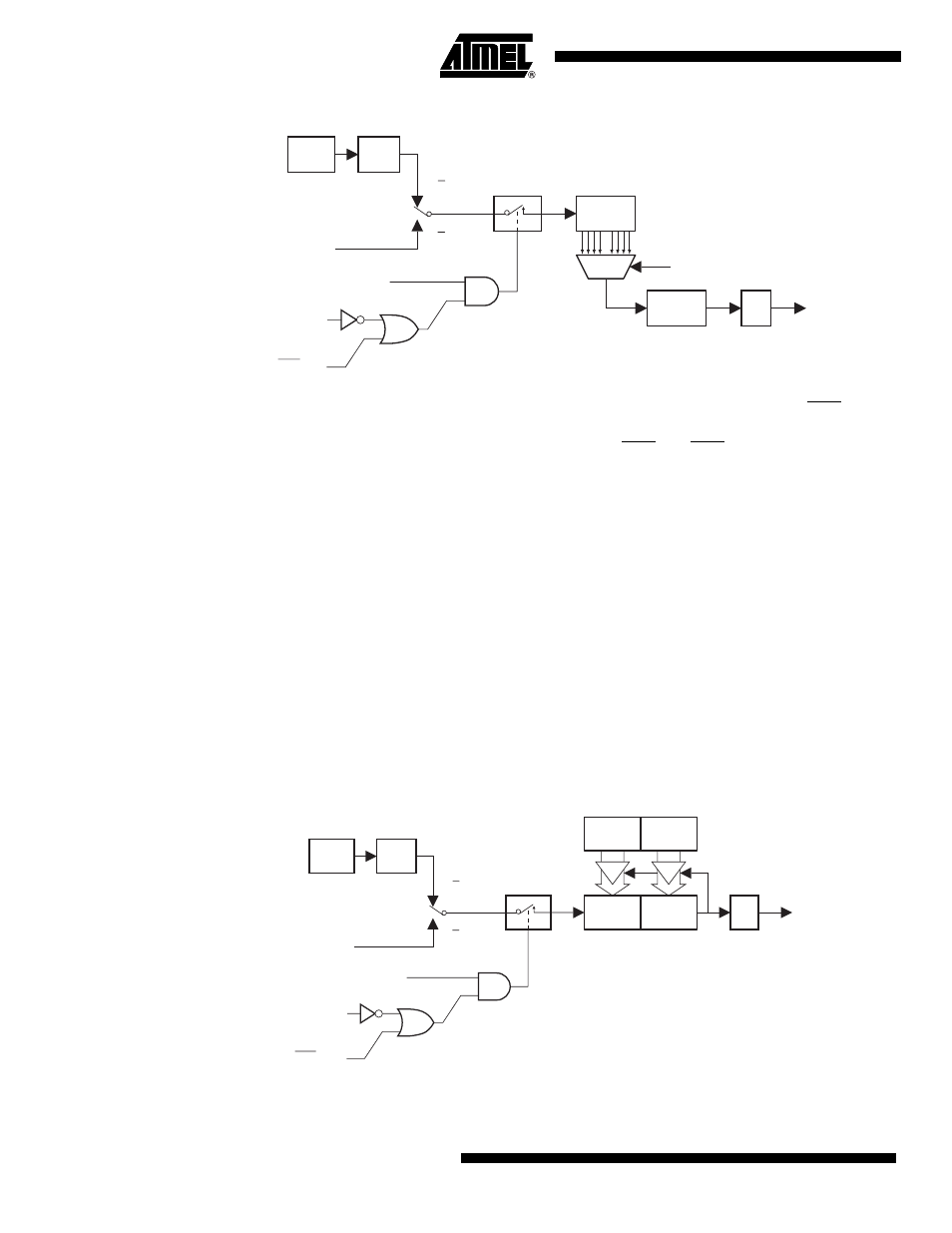
Mode 1 – 16-bit Auto-Reload Timer/Counter
In Mode 1 the Timers are configured for 16-bit auto-reload. The Timer register is run with all
16 bits. The 16-bit reload value is stored in the high and low reload registers (RH1/RL1). The
clock is applied to the combined high and low timer registers (TH1/TL1). As clock pulses are
received, the timer counts up: 0000H, 0001H, 0002H, etc. An overflow occurs on the FFFFH-to-
0000H transition, upon which the timer register is reloaded with the value from RH1/RL1 and the
overflow flag bit in TCON is set. See
. The reload registers default to 0000H, which
gives the full 16-bit timer period compatible with the standard 8051. Mode 1 operation is the
same for Timer/Counter 0.
Figure 14-2. Timer/Counter 1 Mode 1: 16-bit Auto-Reload
OSC
T1 Pin
TR1
GATE
INT1 Pin
TL1
(8 Bits)
Control
Interrupt
C/T = 0
C/T = 1
PSC1
TH1
(8 Bits)
TF1
÷TPS
Mode 1:
Time-out Period
65536
RH
0
RL
0
{
,
}
–
(
)
Oscillator Frequency
----------------------------------------------------------
TPS
1
+
(
)
×
=
OSC
T1 Pin
TR1
GATE
INT1 Pin
TL1
(8 Bits)
Control
Interrupt
C/T = 0
C/T =1
TH1
(8 Bits)
TF1
RL1
(8 Bits)
RH1
(8 Bits)
Reload
÷TPS