Rainbow Electronics AT89LP216 User Manual
Page 16
16
3621A–MICRO–6/06
AT89LP216 [Preliminary]
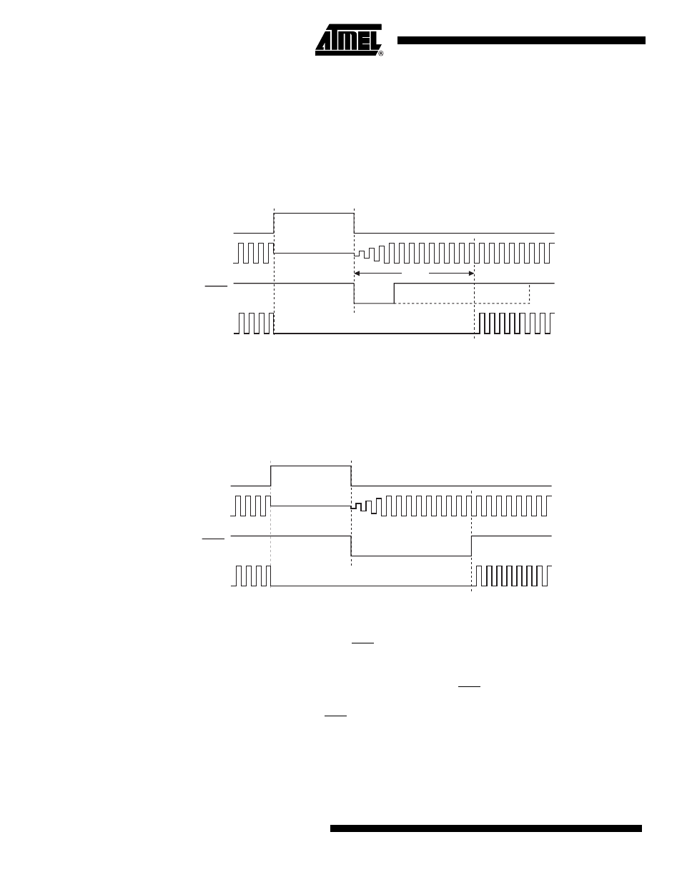
When terminating Power-down by an interrupt, two different wake-up modes are available.
When PWDEX in PCON is zero, the wake-up period is internally timed as shown in
At the falling edge on the interrupt pin, Power-down is exited, the oscillator is restarted, and an
internal timer begins counting. The internal clock will not be allowed to propagate to the CPU
until after the timer has timed out. After the time-out period the interrupt service routine will
begin. The time-out period is controlled by the Start-up Timer Fuses (see
). The interrupt pin need not remain low for the entire time-out period.
Figure 11-1. Interrupt Recovery from Power-down (PWDEX = 0)
When PWDEX = “1”, the wake-up period is controlled externally by the interrupt. Again, at the
falling edge on the interrupt pin, power-down is exited and the oscillator is restarted. However,
the internal clock will not propagate until the rising edge of the interrupt pin as shown in
. The interrupt pin should be held low long enough for the selected clock source to stabilize.
After the rising edge on the pin the interrupt service routine will be executed.
Figure 11-2. Interrupt Recovery from Power-down (PWDEX = 1)
11.2.2
Reset Recovery from Power-down
The wake-up from Power-down through an external reset is similar to the interrupt with
PWDEX = “0”. At the falling edge of RST, Power-down is exited, the oscillator is restarted, and
an internal timer begins counting as shown in
. The internal clock will not be allowed
to propagate to the CPU until after the timer has timed out. The time-out period is controlled by
the Start-up Timer Fuses. (See
). If RST returns high before the time-out,
a two clock cycle internal reset is generated when the internal clock restarts. Otherwise, the
device will remain in reset until RST is brought high.
PWD
INT1
XTAL1
tSUT
Internal
Clock
PWD
INT1
XTAL1
Internal
Clock