Rainbow Electronics AT89LP216 User Manual
Page 31
31
3621A–MICRO–6/06
AT89LP216 [Preliminary]
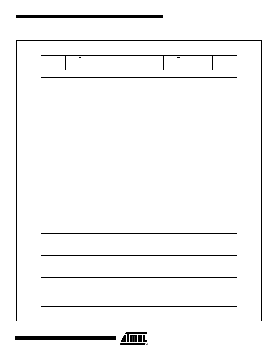
Table 14-2.
TMOD: Timer/Counter Mode Control Register
TMOD = 88H
Reset Value = 0000 0000B
Not
Bit
Addressable
GATE
C/T
M1
M0
GATE
C/T
M1
M0
7
6
5
4
3
2
1
0
Timer1
Timer0
Gate
Gating control when set. Timer/Counter x is enabled only
while INTx pin is high and TRx control pin is set. When
cleared, Timer x is enabled whenever TRx control bit
is set.
Timer 0 gate bit
C/T
Timer or Counter Selector cleared for Timer operation
(input from internal system clock). Set for Counter
operation (input from Tx input pin).
Timer 0 counter/timer select bit
M1
Timer 1 Mode bit 1
Timer 0 M1 bit
M0
Timer 1 Mode bit 0
Timer 0 M0 bit
M1
M0
Mode
Operating Mode
0
0
0
Variable 9 - 16-bit Timer Mode.
8-bit Timer/Counter THx with TLx as 1 - 8-bit prescaler.
0
1
1
16-bit Auto-Reload Mode.
16-bit Timer/Counters THx and TLx are cascaded; there is no prescaler.
1
0
2
8-bit Auto Reload.
8-bit auto-reload Timer/Counter THx holds a value which is to be
reloaded into TLx each time it overflows.
1
1
3
Split Timer Mode.
(Timer 0) TL0 is an 8-bit Timer/Counter controlled by the standard
Timer 0 control bits. TH0 is an 8-bit timer only controlled by Timer 1
control bits.
1
1
3
(Timer 1) Timer/Counter 1 stopped.
Timer SFR
Purpose
Address
Bit-Addressable
TCON
Control
88H
Yes
TMOD
Mode
89H
No
TL0
Timer 0 low-byte
8AH
No
TL1
Timer 1 low-byte
8BH
No
TH0
Timer 0 high-byte
8CH
No
TH1
Timer 1 high-byte
8DH
No
TCONB
Mode
91H
No
RL0
Timer 0 reload low-byte
92H
No
RL1
Timer 1 reload low-byte
93H
No
RH0
Timer 0 reload high-byte
94H
No
RH1
Timer 1 reload high-byte
95H
No