1 interrupt response time – Rainbow Electronics AT89LP216 User Manual
Page 19
19
3621A–MICRO–6/06
AT89LP216 [Preliminary]
12.1
Interrupt Response Time
The interrupt flags may be set by their hardware in any clock cycle. The interrupt controller polls
the flags in the last clock cycle of the instruction in progress. If one of the flags was set in the
preceding cycle, the polling cycle will find it and the interrupt system will generate an LCALL to
the appropriate service routine as the next instruction, provided that the interrupt is not blocked
by any of the following conditions: an interrupt of equal or higher priority level is already in
progress; the instruction in progress is RETI or any write to the IE, IP, or IPH registers. Either of
these conditions will block the generation of the LCALL to the interrupt service routine. The sec-
ond condition ensures that if the instruction in progress is RETI or any access to IE, IP or IPH,
then at least one more instruction will be executed before any interrupt is vectored to. The poll-
ing cycle is repeated at the last cycle of each instruction, and the values polled are the values
that were present at the previous clock cycle. If an active interrupt flag is not being serviced
because of one of the above conditions and is no longer active when the blocking condition is
removed, the denied interrupt will not be serviced. In other words, the fact that the interrupt flag
was once active but not serviced is not remembered. Every polling cycle is new.
If a request is active and conditions are met for it to be acknowledged, a hardware subroutine
call to the requested service routine will be the next instruction executed. The call itself takes
four cycles. Thus, a minimum of five complete clock cycles elapsed between activation of an
interrupt request and the beginning of execution of the first instruction of the service routine. A
longer response time results if the request is blocked by one of the previously listed conditions. If
an interrupt of equal or higher priority level is already in progress, the additional wait time
depends on the nature of the other interrupt's service routine. If the instruction in progress is not
in its final clock cycle, the additional wait time cannot be more than 3 cycles, since the longest
are only 4 cycles long. If the instruction in progress is RETI or an access to IE or IP, the addi-
tional wait time cannot be more than 7 cycles (a maximum of three more cycles to complete the
instruction in progress, plus a maximum of 4 cycles to complete the next instruction). Thus, in a
single-interrupt system, the response time is always more than 5 clock cycles and less than 13
clock cycles. See
and
.
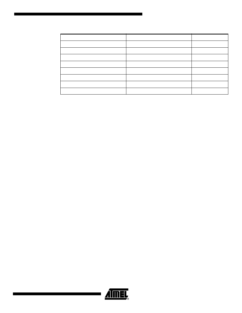
Table 12-1.
Interrupt Vector Addresses
Interrupt
Source
Vector Address
System Reset
RST or POR or BOD
0000H
External Interrupt 0
IE0
0003H
Timer 0 Overflow
TF0
000BH
External Interrupt 1
IE1
0013H
Timer 1 Overflow
TF1
001BH
Serial Port
RI or TI or SPIF
0023H
General-purpose Interrupt
GPIF
002BH
Analog Comparator
CF
0033H