Port d as general digital i/o, Attiny28l/v – Rainbow Electronics ATtiny28L User Manual
Page 43
43
ATtiny28L/V
1062E–10/01
Port D as General Digital I/O
All eight pins in Port D have equal functionality when used as digital I/O pins.
PDn, general I/O pin: The DDDn bit in the DDRD register selects the direction of this pin.
If DDDn is set (one), PDn is configured as an output pin. If DDDn is cleared (zero), PDn
is configured as an input pin. If PDn is set (one) when configured as an input pin, the
MOS pull-up resistor is activated. To switch the pull-up resistor off, the PDn has to be
cleared (zero), or the pin has to be configured as an output pin. The port pins are tri-
stated when a reset condition becomes active, even if the clock is not running.
Note:
n: 7,6,...,0, pin number
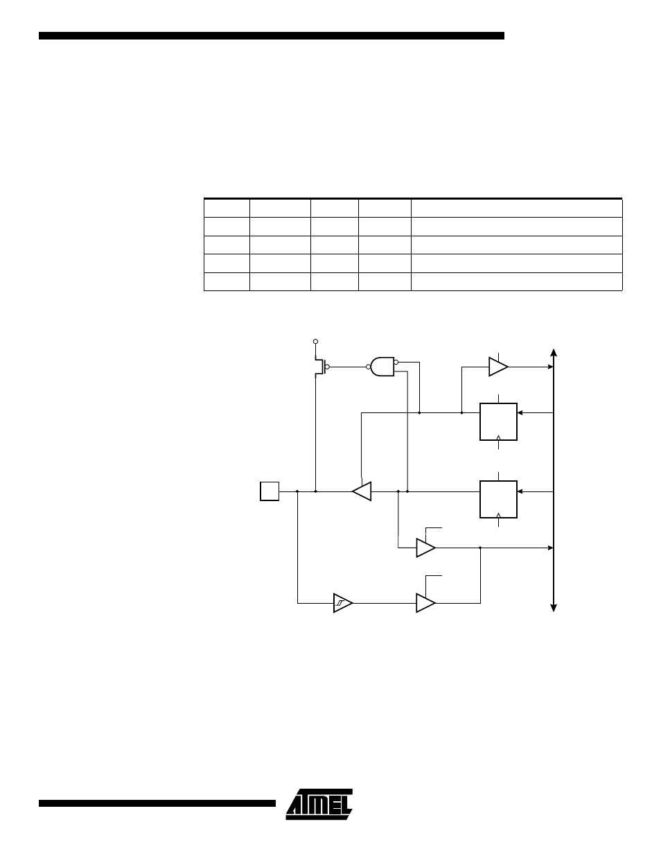
Figure 35. Port D Schematic Diagram (Pins PD7 - PD0)
Table 19. DDDn Bits on Port D Pins
DDDn
PORTDn
I/O
Pull-up
Comment
0
0
Input
No
Tri-state (high-Z)
0
1
Input
Yes
PDn will source current if ext. pulled low
1
0
Output
No
Push-pull Zero Output
1
1
Output
NO
Push-pull One Output
DA
T
A
BUS
D
D
Q
Q
RESET
RESET
C
C
WD
WP
RD
MOS
PULL-
UP
PDn
R
R
WP:
WD:
RL:
RP:
RD:
WRITE PORTD
WRITE DDRD
READ PORTD LATCH
READ PORTD PIN
READ DDRD
DDDn
PORTDn
RL
RP
n :
0 - 7