Reset sources, Attiny28l/v – Rainbow Electronics ATtiny28L User Manual
Page 13
13
ATtiny28L/V
1062E–10/01
The most typical and general program setup for the Reset and Interrupt vector
addresses are:
Address
Labels
Code
Comments
$000
rjmp
RESET
; Reset handler
$001
rjmp
EXT_INT0
; IRQ0 handler
$002
rjmp
EXT_INT1
; IRQ1 handler
$003
rjmp
LOW_LEVEL
; Low level input handler
$004
rjmp
TIM0_OVF
; Timer0 overflow handle
$005
rjmp
ANA_COMP
; Analog Comparator handle
;
$006
MAIN:
xxx
; Main program start
…
…
…
…
Reset Sources
The ATtiny28 provides three sources of reset:
•
Power-on Reset. The MCU is reset when the supply voltage is below the Power-on
Reset threshold (V
POT
).
•
External Reset. The MCU is reset when a low level is present on the RESET pin for
more than 50 ns.
•
Watchdog Reset. The MCU is reset when the Watchdog Timer period expires and
the Watchdog is enabled.
During reset, all I/O registers are then set to their initial values and the program starts
execution from address $000. The instruction placed in address $000 must be an RJMP
(relative jump) instruction to the reset handling routine. If the program never enables an
interrupt source, the interrupt vectors are not used, and regular program code can be
placed at these locations. The circuit diagram in Figure 15 shows the reset logic. Table 4
defines the timing and electrical parameters of the reset circuitry.
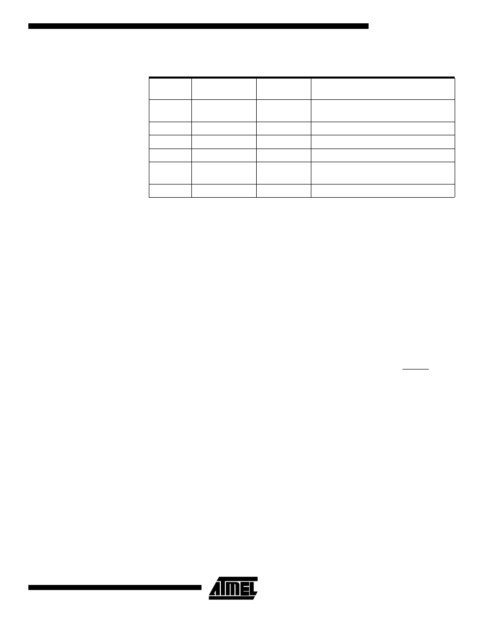
Table 3. Reset and Interrupt Vectors
Vector
No.
Program
Address
Source
Interrupt Definition
1
$000
RESET
Hardware Pin, Power-on Reset and
Watchdog Reset
2
$001
INT0
External Interrupt Request 0
3
$002
INT1
External Interrupt Request 1
4
$003
Input Pins
Low-level Input on Port B
5
$004
TIMER0,
OVF0
Timer/Counter0 Overflow
6
$005
ANA_COMP
Analog Comparator