Clock options, Internal rc oscillator, Crystal oscillator – Rainbow Electronics ATtiny28L User Manual
Page 4: Attiny28l/v
4
ATtiny28L/V
1062E–10/01
Clock Options
The device has the following clock source options, selectable by Flash Fuse bits as
shown in Table 1.
Note:
“1” means unprogrammed, “0” means programmed.
The various choices for each clocking option give different start-up times as shown in
Table 5 on page 14.
Internal RC Oscillator
The internal RC oscillator option is an on-chip calibrated oscillator running at a nominal
frequency of 1.2 MHz. If selected, the device can operate with no external components.
The device is shipped with this option selected.
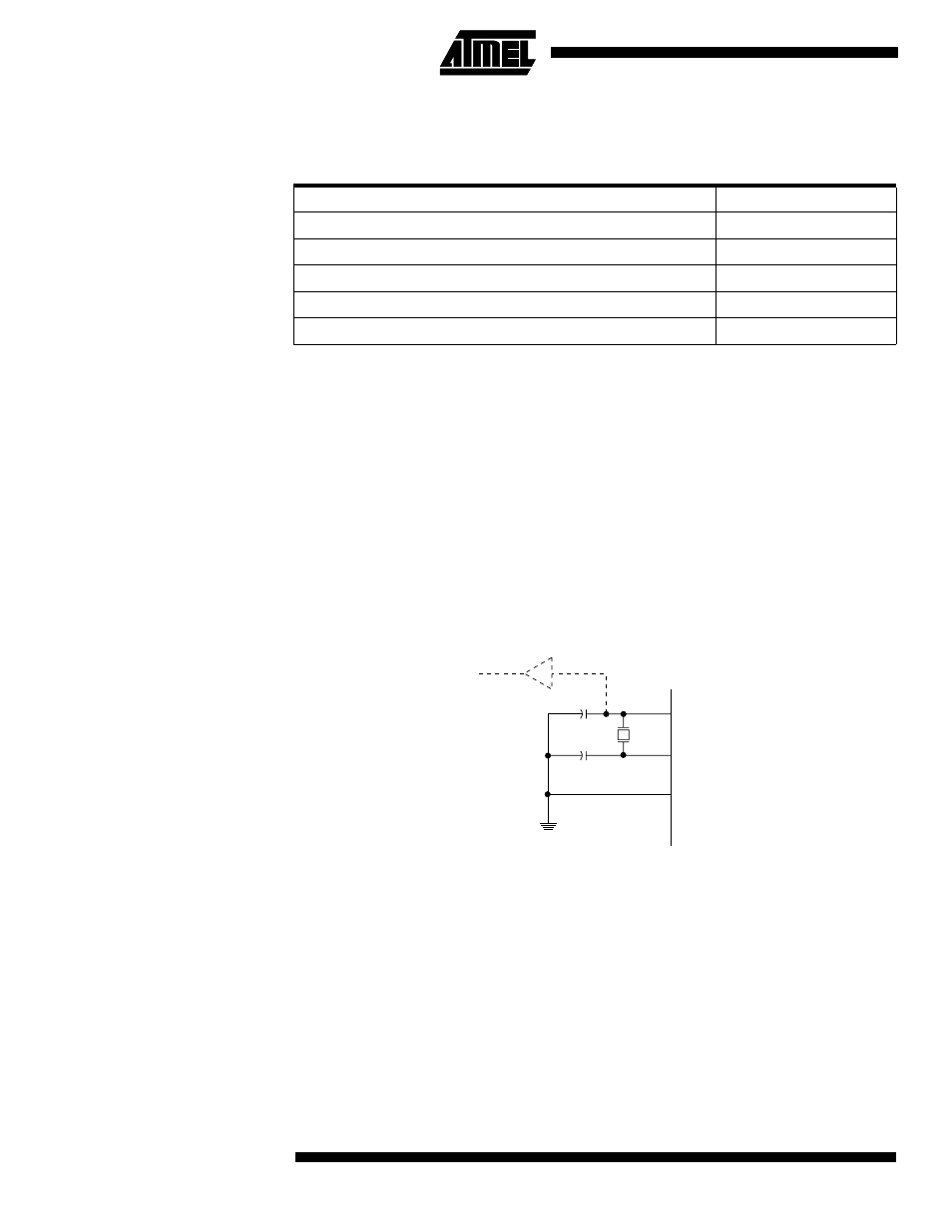
Crystal Oscillator
XTAL1 and XTAL2 are input and output, respectively, of an inverting amplifier, which
can be configured for use as an on-chip oscillator, as shown in Figure 2. Either a quartz
crystal or a ceramic resonator may be used. When the INTCAP fuse is programmed,
internal load capacitors with typical values 50 pF are connected between XTAL1/XTAL2
and ground.
Figure 2. Oscillator Connections
Note:
1. When using the MCU oscillator as a clock for an external device, an HC buffer should
be connected as indicated in the figure.
Table 1. Device Clocking Option Select
Clock Option
CKSEL3..0
External Crystal/Ceramic Resonator
1111 - 1010
External Low-frequency Crystal
1001 - 1000
External RC Oscillator
0111 - 0101
Internal RC Oscillator
0100 - 0010
External Clock
0001 - 0000
XTAL2
XTAL1
GND
C2
C1
MAX 1 HC BUFFER
HC