Watchdog timer, Watchdog timer control register – wdtcr, Attiny28l/v – Rainbow Electronics ATtiny28L User Manual
Page 26
26
ATtiny28L/V
1062E–10/01
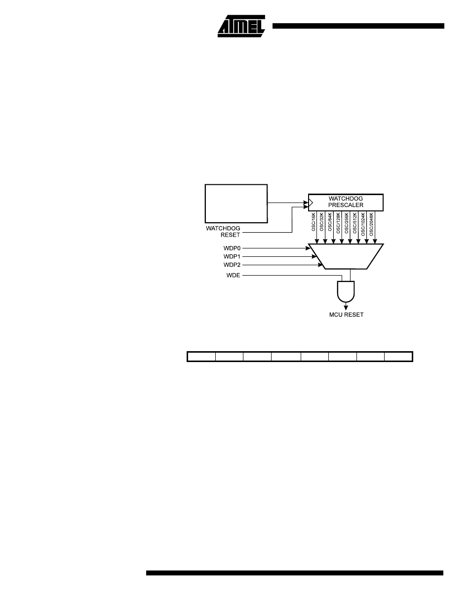
Watchdog Timer
The Watchdog Timer is clocked from a separate on-chip oscillator. By controlling the
Watchdog Timer prescaler, the Watchdog reset interval can be adjusted as shown in
Table 11. See characterization data for typical values at other V
CC
levels. The WDR
(Watchdog Reset) instruction resets the Watchdog Timer. Eight different clock cycle
periods can be selected to determine the reset period. If the reset period expires without
another Watchdog reset, the ATtiny28 resets and executes from the reset vector. For
timing details on the Watchdog reset, refer to page 17.
To prevent unintentional disabling of the Watchdog, a special turn-off sequence must be
followed when the Watchdog is disabled. Refer to the description of the Watchdog Timer
Control Register for details.
Figure 22. Watchdog Timer
Watchdog Timer Control
Register – WDTCR
• Bits 7..5 - Res: Reserved Bits
These bits are reserved bits in the ATtiny28 and will always read as zero.
• Bit 4 – WDTOE: Watchdog Turn-off Enable
This bit must be set (one) when the WDE bit is cleared. Otherwise, the Watchdog will
not be disabled. Once set, hardware will clear this bit to zero after four clock cycles.
Refer to the description of the WDE bit for a Watchdog disable procedure.
• Bit 3 – WDE: Watchdog Enable
When the WDE is set (one), the Watchdog Timer is enabled and if the WDE is cleared
(zero), the Watchdog Timer function is disabled. WDE can only be cleared if the
WDTOE bit is set (one). To disable an enabled Watchdog Timer, the following proce-
dure must be followed:
1.
In the same operation, write a logical “1” to WDTOE and WDE. A logical “1” must
be written to WDE even though it is set to one before the disable operation starts.
2.
Within the next four clock cycles, write a logical “0” to WDE. This disables the
Watchdog.
1 MHz at V
CC
= 5V
350 kHz at V
CC
= 3V
110 kHz at V
CC
= 2V
Oscillator
Bit
7
6
5
4
3
2
1
0
$01
–
–
–
WDTOE
WDE
WDP2
WDP1
WDP0
WDTCR
Read/Write
R
R
R
R/W
R/W
R/W
R/W
R/W
Initial Value
0
0
0
0
0
0
0
0