Transmitter – Rainbow Electronics MAX7032 User Manual
Page 16
MAX7032
Low-Cost, Crystal-Based, Programmable,
ASK/FSK Transceiver with Fractional-N PLL
16
______________________________________________________________________________________
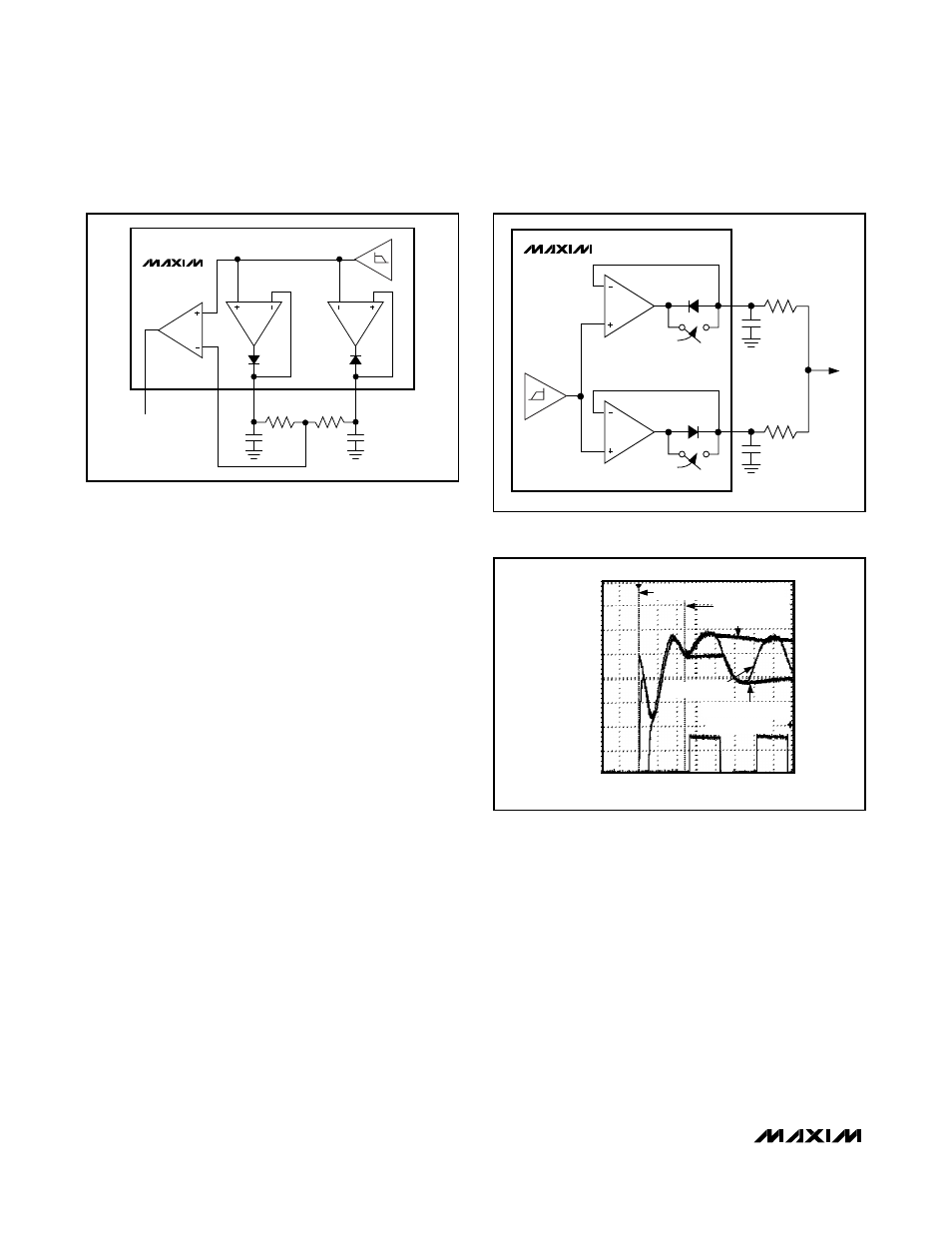
The maximum and minimum peak detectors can be
used together to form a data slicer threshold voltage at
a value midway between the maximum and minimum
voltage levels of the data stream (see the Data Slicer
section and Figure 4). The RC time constant of the
peak-detector combining network should be set to at
least 5 times the data period.
If there is an event that causes a significant change in
the magnitude of the baseband signal, such as an AGC
gain switch or a power-up transient, the peak detectors
may “catch” a false level. If a false peak is detected,
the slicing level is incorrect. The MAX7032 has a fea-
ture called peak-detector track enable (TRK_EN),
where the peak-detector outputs can be reset (see
Figure 5). If TRK_EN is set (logic 1), both the maximum
and minimum peak detectors follow the input signal.
When TRK_EN is cleared (logic 0), the peak detectors
revert to their normal operating mode. The TRK_EN
function is automatically enabled for a short time when-
ever the IC is first powered up, or transitions from trans-
mit to receive mode, or recovers from the sleep portion
of DRX mode, or when an AGC gain switch occurs
regardless of the bit setting. Since the peak detectors
exhibit a fast-attack/slow-decay response, this feature
allows for an extremely fast startup or AGC recovery.
See Figure 6 for an illustration of a fast-recovery
sequence. In addition to the automatic control of this
function, the TRK_EN bits can be controlled through the
serial interface (see the Serial Control Interface section).
Transmitter
Power Amplifier (PA)
The PA of the MAX7032 is a high-efficiency, open-
drain, Class C amplifier. The PA with proper output-
matching network can drive a wide range of antenna
impedances, which includes a small-loop PC board
trace and a 50
Ω antenna. The output-matching network
for a 50
Ω antenna is shown in the Typical Application
Circuit. The output-matching network suppresses the
carrier harmonics and transforms the antenna imped-
ance to an optimal impedance at PAOUT (pin 5). The
optimal impedance at PAOUT is 250
Ω.
When the output-matching network is properly tuned, the
PA transmits power with a high overall efficiency of up to
32%. The efficiency of the PA itself is more than 46%.
The output power is set by an external resistor at
PAOUT, and is also dependent on the external antenna
and antenna-matching network at the PA output.
MAX7032
PDMIN
TO SLICER
INPUT
BASEBAND
FILTER
MINIMUM PEAK
DETECTOR
MAXIMUM PEAK
DETECTOR
PDMAX
TRK_EN = 1
TRK_EN = 1
Figure 5. Peak-Detector Track Enable
Figure 6. Fast Receiver Recovery in FSK Mode Utilizing Peak
Detectors
200mV/div
DATA OUTPUT
2V/div
MIN PEAK DETECTOR
MAX PEAK DETECTOR
RECEIVER ENABLED, TRK_EN SET
TRK_EN CLEARED
FILTER OUTPUT
DATA OUTPUT
100
µs/div
MAX7032
C
PDMAX
PDMIN
R
C
R
DATA
SLICER
DATA
PEAK
DET
PEAK
DET
Figure 4. Generating Data Slicer Threshold Using the Peak
Detectors