Rainbow Electronics MAX5440 User Manual
General description, Applications, Features
General Description
The MAX5440 dual, 40k
Ω logarithmic taper volume con-
trol features a debounced up/down interface for use
with a simple rotary encoder without using a microcon-
troller (µC). Each potentiometer has 32 log-spaced tap
points with a buffered wiper output and replaces
mechanical potentiometers. An integrated bias genera-
tor provides the required ((V
DD
+ V
SS
) / 2) bias voltage,
eliminating the need for costly external op-amp circuits
in unipolar audio applications. A mode-indicator LED
output specifies volume or balance control. Five inte-
grated LED drivers indicate volume level or balance set-
tings, depending on the status of the mode indicator.
The MAX5440 includes debounced pushbutton inputs
for mute and mode. The mute input allows a single
pushbutton to change between volume control and the
-90dB (typ) mute setting. The mode input toggles
between volume and balance control. A click-and-pop
suppression feature minimizes the audible noise gener-
ated by wiper transitions. The MAX5440 provides a
nominal temperature coefficient of 35ppm/°C end-to-
end and 5ppm/°C, ratiometrically. The MAX5440 is
available in a 24-pin SSOP package and is specified for
operation over the -40°C to +85°C extended tempera-
ture range.
Applications
Stereo Volume Control
Desktop Speakers
Multimedia Docking Stations
Set-Top Boxes
Automotive Back-Seat Multimedia
Features
♦ Logarithmic Taper Volume Control with (31) 2dB
Steps
♦ Low-Power Wiper Buffers Provide 0.003% THD
♦ Single +2.7V to +5.5V or Dual ±2.7V Supply
Voltage Operation
♦ Low 0.5µA Shutdown Supply Current
♦ Integrated Bias Voltage Generator
♦ Five-Segment LED Volume/Balance Indicator
♦ Clickless Switching
♦ 40kΩ End-to-End Fixed Resistance Value
♦ Mute Function Toggles to -90dB (typ)
♦ Power-On Reset to -12dBFS Wiper Position
MAX5440
Stereo Volume Control
with Rotary Encoder Interface
________________________________________________________________ Maxim Integrated Products
1
24
23
22
21
20
19
17
1
2
3
4
5
6
8
GND
MODEIND
LEDIND4
LEDIND3
V
LOGIC
V
SS
V
DD
MUTE
RENCODEB
RENCODEA
TOP VIEW
MAX5440
LEDIND2
LEDIND1
H1
H0
SHDN
18
7
LEDIND0
GND
15
10
W1
W0
16
9
L1
L0
13
12
BIAS
14
11
MIDBIAS
MODE
SSOP
Pin Configuration
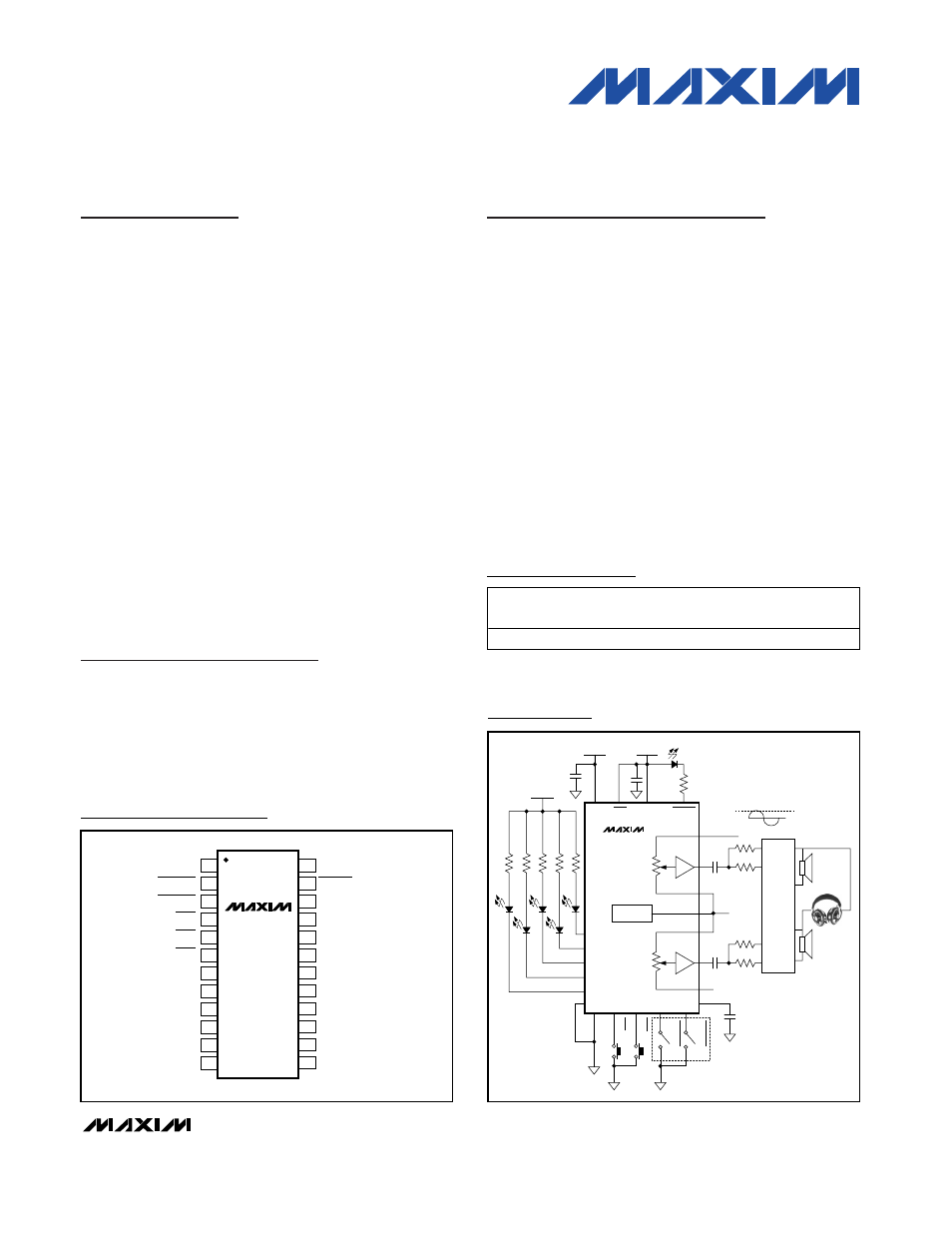
V
DD
V
SS
(V
DD +
V
SS
) / 2
(V
DD +
V
SS
) / 2
V
LOGIC
V
PEAK
H1
L1
W1
SHDN
LEFT INPUT
RIGHT INPUT
MODEIND
HEADPHONE
DRIVER
L0
H0
W0
V
LOGIC
LEDIND4
LEDIND3
LEDIND0
GND
MUTE
MODE
RENCODEA
RENCODEA
LEDIND1
LEDIND2
ROTARY
ENCODER
MIDBIAS
BIAS
MAX5440
Typical Operating Circuit
19-0542; Rev 0; 5/06
Ordering Information
PART
TEMP RANGE
PIN-PACKAGE
PKG
CODE
MAX5440EAG
-40°C to +85°C
24 SSOP
A24-1
For pricing, delivery, and ordering information, please contact Maxim/Dallas Direct! at
1-888-629-4642, or visit Maxim’s website at www.maxim-ic.com.