Rainbow Electronics MAX17409 User Manual
Page 23
MAX17409
1-Phase Quick-PWM GPU Controller
______________________________________________________________________________________
23
Power-Up Sequence (POR, UVLO)
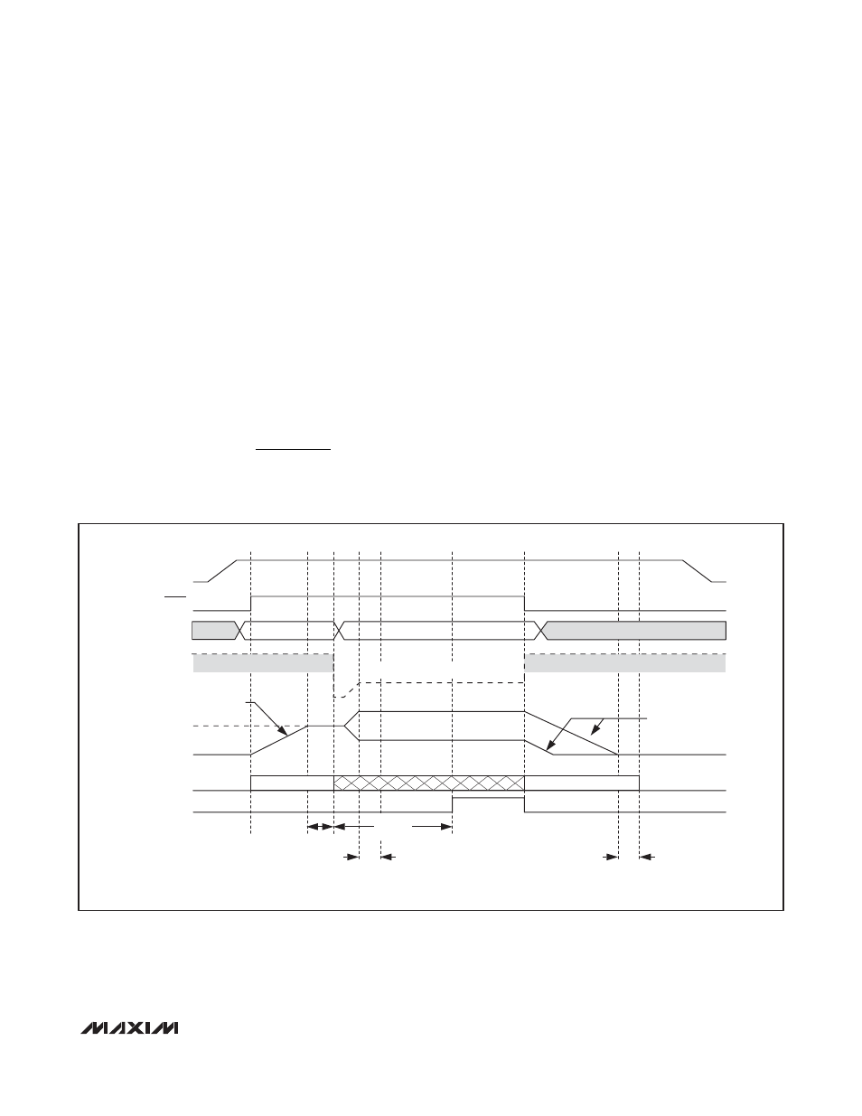
The MAX17409 is enabled when SHDN is driven high
(Figure 6). The reference powers up first. Once the ref-
erence exceeds its UVLO threshold, the internal analog
blocks are turned on and masked by a 150µs one-shot
delay. The PWM controller then begins switching.
Power-on reset (POR) occurs when V
CC
rises above
approximately 2V, resetting the fault latch and prepar-
ing the controller for operation. The V
CC
UVLO circuitry
inhibits switching until V
CC
rises above 4.25V. The con-
troller powers up the reference once the system
enables the controller, V
CC
is above 4.25V, and SHDN
is driven high. With the reference in regulation, the con-
troller ramps the output voltage to the selected VID volt-
age with a 1.56mV/µs slew rate:
where V
BOOT
is the initial VID target. The soft-start cir-
cuitry does not use a variable current limit, so full output
current is available immediately. PWRGD becomes
high impedance approximately 5ms after the target out-
put voltage is reached. The MAX17409 automatically
uses pulse-skipping mode during soft-start and uses
forced-PWM mode during soft-shutdown, regardless of
the SKIP configuration.
For automatic startup, the battery voltage should be
present before V
CC
. If the controller attempts to bring
the output into regulation without the battery voltage
present, the fault latch trips. The controller remains shut
down until the fault latch is cleared by toggling SHDN
or cycling the V
CC
power supply below 0.5V.
If the V
CC
voltage drops below 4.25V, the controller
assumes that there is not enough supply voltage to
make valid decisions. To protect the output from over-
voltage faults, the controller shuts down immediately
and forces a high-impedance output (DL and DH
pulled low).
t
V
mV µs
TRAN START
BOOT
(
)
.
/
=
(
)
1 56
PWRGD
INTERNAL
PWM CONTROL
OVP LEVEL
V
CC
G0–G5
t
BLANK
60
µs TYP
t
BLANK
20
µs TYP
t
BLANK
20
µs TYP
t
BLANK
5ms TYP
OVP TRACKS INTERNAL TARGET
FORCED-PWM
SHDN
INVALID VID
INVALID VID CODE
SOFT-START =
1.56mV/
µs SLEW RATE
SOFT-SHUTDOWN =
1.56mV/
µs SLEW RATE
PULSE SKIPPING
INITIAL TARGET
V
CORE
OVP = 1.45V MIN
OVP = 1.45V MIN
Figure 6. Power-Up and Shutdown Sequence Timing Diagram