Rainbow Electronics MAX17409 User Manual
Page 22
MAX17409
1-Phase Quick-PWM GPU Controller
22
______________________________________________________________________________________
Forced-PWM Operation (Normal Mode)
During soft-shutdown and normal operation—when the
CPU is actively running (SKIP = low, Table 3)
—
the
MAX17409 operates with the low-noise, forced-PWM
control scheme. Forced-PWM operation disables the
zero-crossing comparator, forcing the low-side gate-
drive waveforms to constantly be the complement of
the high-side gate-drive waveforms. This keeps the
switching frequency constant and allows the inductor
current to reverse under light loads, providing fast,
accurate negative-output-voltage transitions by quickly
discharging the output capacitors.
Forced-PWM operation comes at a cost: the no-load
+5V bias supply current remains between 10mA to
50mA, depending on the external MOSFETs and
switching frequency. To maintain high efficiency under
light-load conditions, the processor might switch the
controller to a low-power pulse-skipping control
scheme after entering suspend mode. The MAX17409
automatically uses pulse-skipping operation during
soft-start, regardless of the SKIP configuration.
Light-Load Pulse-Skipping Operation
During soft-start and sleep states—SKIP is pulled
high—the MAX17409 operates in pulse-skipping mode.
The pulse-skipping mode enables the driver’s zero-
crossing comparator, so the controller pulls DL low
when its current-sense inputs detect “zero” inductor
current. This keeps the inductor from sinking current
and discharging the output capacitors and forces the
controller to skip pulses under light-load conditions to
avoid overcharging the output.
Upon entering pulse-skipping operation, the controller
temporarily blanks the upper PWRGD thresholds, and
sets the OVP threshold to 1.80V to prevent false OVP
faults when the transition to pulse-skipping operation
coincides with a VID DAC code. The MAX17409 auto-
matically uses forced-PWM operation during soft-shut-
down, regardless of the SKIP configuration.
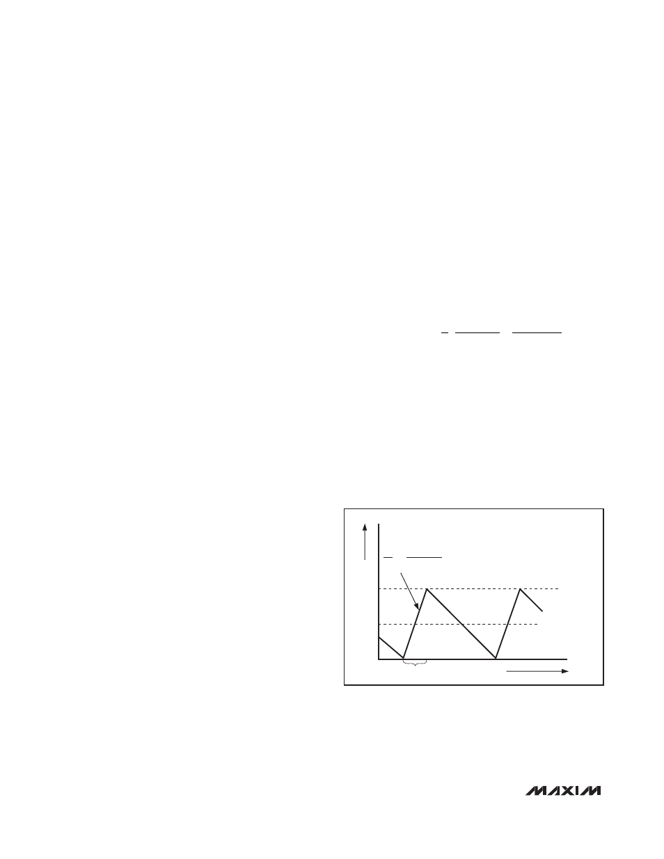
Automatic Pulse-Skipping Switchover
In skip mode (SKIP = high), an inherent automatic
switchover to PFM takes place at light loads. This
switchover is affected by a comparator that truncates
the low-side switch on-time at the inductor current’s
zero crossing. The zero-crossing comparator senses
the inductor current across the low-side MOSFETs.
Once V
LX
drops below the zero-crossing comparator
threshold (see the
Electrical Characteristics
table), the
comparator forces DL low (Figure 2). This mechanism
causes the threshold between pulse-skipping PFM and
nonskipping-PWM operation to coincide with the
boundary between continuous and discontinuous induc-
tor-current operation. The PFM/PWM crossover occurs
when the load current is equal to 1/2 the peak-to-peak
ripple current, which is a function of the inductor value
(Figure 5). For a 7V to 20V battery input range, this
threshold is relatively constant, with only a minor depen-
dence on the input voltage due to the typically low duty
cycles. The total load current at the PFM/PWM
crossover threshold (I
LOAD(SKIP)
) is approximately:
The switching waveforms might appear noisy and asyn-
chronous when light loading activates pulse-skipping
operation, but this is a normal operating condition that
results in high light-load efficiency. Trade-offs between
PFM noise and light-load efficiency are made by varying
the inductor value. Generally, low inductor values pro-
duce a broader efficiency vs. load curve, while higher
values result in higher full-load efficiency (assuming that
the coil resistance remains fixed) and less output volt-
age ripple. Penalties for using higher inductor values
include larger physical size and degraded load-tran-
sient response, especially at low input-voltage levels.
I
t
V
L
V
V
V
LOAD SKIP
SW OUT
IN
OUT
IN
(
)
= ⎛
⎝⎜
⎞
⎠⎟
⎛
⎝⎜
⎞
1
2
-
⎠⎠⎟
INDUCTOR CURRENT
I
LOAD
= I
PEAK
/2
ON-TIME
0
TIME
I
PEAK
L
V
BATT
- V
OUT
∆I
∆t
=
Figure 5. Pulse-Skipping/Discontinuous Crossover Point