Pin description (continued) – Rainbow Electronics MAX17409 User Manual
Page 12
MAX17409
1-Phase Quick-PWM GPU Controller
12
______________________________________________________________________________________
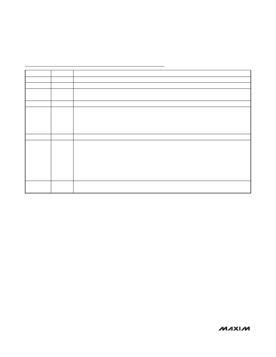
Pin Description (continued)
PIN
NAME
FUNCTION
22
DH
High-Side Gate-Driver Output. DH swings from LX to BST. The controller pulls DH low in shutdown.
23
GND
Analog Ground. Internally connected to GND.
24
VRHOT
Thermal Comparator’s Open-Drain Output. The comparator pulls
VRHOT low when the voltage at
THRM drops below 30% of V
CC
(1.5V with 5V V
CC
).
VRHOT is high impedance in shutdown.
25
REF
Buffered 2V Reference Output. Bypass REF with a 100pF to 1000pF capacitor. Do not exceed 1000pF.
26 ILIM
Valley Current-Limit Adjustment Input. The valley current-limit threshold voltage at CSP to CSN
equals precisely 1/10 of the differential REF to ILIM voltage over a 0.1V to 0.5V range (10mV to 50mV
current-sense range). The negative current-limit threshold is nominally -125% of the corresponding
valley current-limit threshold.
Connect ILIM directly to V
CC
to set the default 22.5mV current-limit threshold setting.
27 V
CC
Analog Supply Voltage. Connect to a 4.5V to 5.5V source. Bypass to GND with a 1µF minimum capacitor.
28 CCV
Integrator Capacitor Connection. Connect a capacitor (C
CCV
) from CCV to GND to set the integration
time constant. Choose the capacitor value according to:
16
x [C
CCV
/G
m(CCV)
] x f
SW
>> 1
where G
m(CCV)
= 320
S (max) is the integrator’s transconductance and f
SW
is the switching
frequency set by the R
TON
resistance.
The integrator is internally disabled during any downward output-voltage transition that occurs in
pulse-skipping mode, and remains disabled until the transition blanking period expires and the
output reaches regulation (error-amplifier transition detected).
— EP
Exposed Pad (Backside). Internally connected to the substrate. Connect to the ground plane through
a thermally enhanced via.