Rainbow Electronics MAX17409 User Manual
Page 21
MAX17409
1-Phase Quick-PWM GPU Controller
______________________________________________________________________________________
21
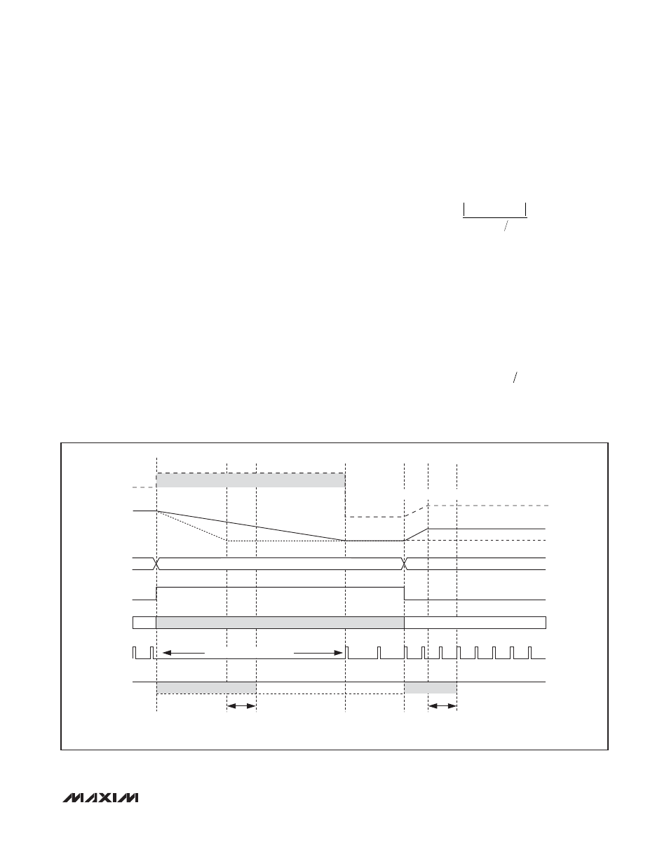
Output-Voltage Transition Timing
The MAX17409 performs mode transitions in a controlled
manner, automatically minimizing input surge currents.
This feature allows the circuit designer to achieve nearly
ideal transitions, guaranteeing just-in-time arrival at the
new output voltage level with the lowest possible peak
currents for a given output capacitance.
At the beginning of an output-voltage transition, the
MAX17409 blanks both PWRGD thresholds, preventing
the PWRGD open-drain output from changing states
during the transition. The controller enables the
PWRGD thresholds approximately 20µs after the slew-
rate controller reaches the target output voltage. The
slew rate is set to 12.5mV/µs to ensure that the transi-
tion can be completed within a reasonable time period.
The MAX17409 automatically controls the current to the
minimum level required to complete the transition in the
calculated time. The slew-rate controller uses an inter-
nal capacitor and current source to transition the target
voltage. The total transition time depends on the
12.5mV/µs slew rate, the voltage difference, and the
accuracy of the slew-rate controller, C
SLEW
, accuracy).
The slew rate is not dependent on the total output
capacitance, as long as the surge current is less than
the current limit. For all dynamic VID transitions, the
transition time (t
TRAN
) is given by:
where V
OLD
is the original output voltage, and V
NEW
is
the new target voltage. See Slew-Rate Accuracy in the
Electrical Characteristics
for slew-rate limits. For soft-
start and shutdown, the controller automatically
reduces the slew rate to 1.56mV/µs (1/8 of the nominal
slew rate).
The output voltage tracks the slewed target voltage,
making the transitions relatively smooth. The average
inductor current required to make an output voltage
transition is:
where C
OUT
is the total output capacitance.
I
C
mVµs
L
OUT
≅
×12 5
.
t
V
V
mVµs
TRAN
NEW
OLD
=
-
12 5
.
SKIP
PWRGD
INTERNAL
PWM CONTROL
BLANK HIGH-Z
PULSE-SKIPPING MODE
DH
OVP LEVEL
CPU CORE
VOLTAGE
INTERNAL
TARGET
ACTUAL V
OUT
BLANK HIGH-Z
VID (G0–G5)
LOW THRESHOLD ONLY
FORCED-PWM MODE
NEW ACTIVE
VID
LOW VID
HIGH VID
OVP = 1.45V MIN
NO PULSES: V
OUT
> V
TARGET
t
BLANK
20
µs TYP
t
BLANK
20
µs TYP
SLEEP VID
OVP TRACKS INTERNAL TARGET
Figure 4. VID Transition