Feedback adjustment amplifiers – Rainbow Electronics MAX17409 User Manual
Page 18
MAX17409
1-Phase Quick-PWM GPU Controller
18
______________________________________________________________________________________
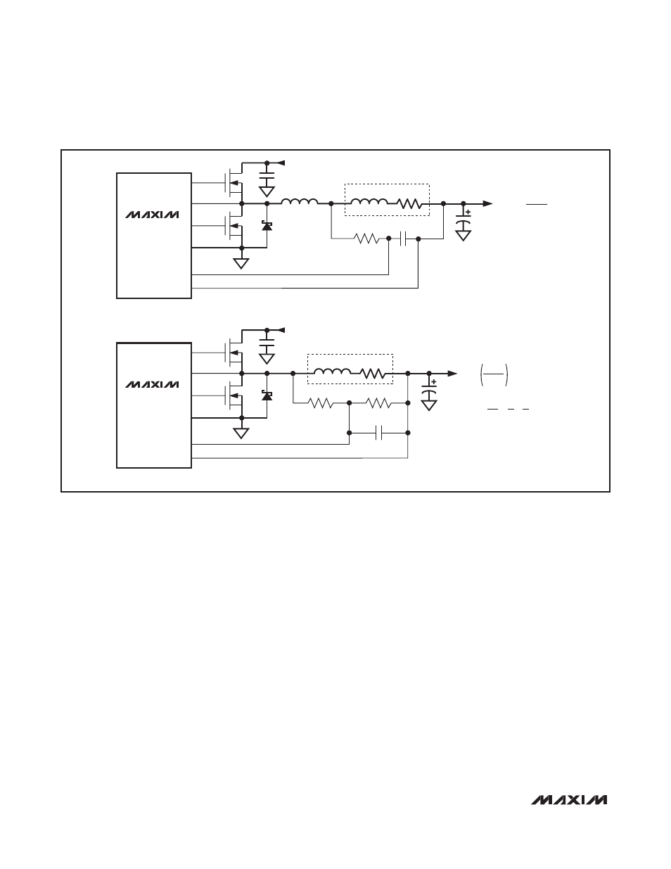
SENSE RESISTOR
L
MAX17409
C
OUT
INPUT (V
IN
)
C
IN
CSN
CSP
PGND
DL
DH
LX
C
EQ
R1
N
H
N
L
D
L
L
ESL
R
SENSE
C
EQ
R1 =
L
SENSE
R
SENSE
MAX17409
C
OUT
INPUT (V
IN
)
C
IN
B) LOSSLESS INDUCTOR SENSING
FOR THERMAL COMPENSATION:
R2 SHOULD CONSIST OF AN NTC RESISTOR IN
SERIES WITH A STANDARD THIN-FILM RESISTOR.
CSN
CSP
PGND
DL
DH
LX
C
EQ
R
1
R
2
N
H
N
L
D
L
L
INDUCTOR
A) OUTPUT SERIES RESISTOR SENSING
R
DCR
R
CS
=
R2
R
DCR
R1 + R2
R
DCR
=
L
[
1 + 1
]
C
EQ
R1 R2
Figure 3. Current-Sense Methods
Feedback Adjustment Amplifiers
Voltage-Positioning Amplifier
(Steady-State DC Droop)
The MAX17409 includes a transconductance amplifier
for adding gain to the voltage-positioning sense path.
The amplifier’s input is generated by the differential cur-
rent-sense inputs, which sense the inductor current by
measuring the voltage across either current-sense
resistors or the inductor’s DCR. The amplifier’s output
connects directly to the regulator’s voltage-positioned
feedback input (FB), so the resistance between FB and
the output-voltage sense point determines the voltage-
positioning gain:
where the target voltage (V
TARGET
) is defined in the
Nominal Output-Voltage Selection
section, and the FB
amplifier’s output current (I
FB
) is determined by the cur-
rent-sense voltages:
I
FB
= G
m(FB)
x (V
CSP
- V
CSN
)
where V
CSP
- V
CSN
is the differential current-sense volt-
age, and G
m(FB)
is typically 600µS, as defined in the
Electrical Characteristics
table.
Differential Remote Sense
The MAX17409 includes differential, remote-sense
inputs to eliminate the effects of voltage drops along the
PCB traces and through the processor’s power pins.
The feedback-sense node connects to the voltage-posi-
tioning resistor (R
FB
). The ground-sense (GNDS) input
connects to an amplifier that adds an offset directly to
the target voltage, effectively adjusting the output volt-
age to counteract the voltage drop in the ground path.
Connect the voltage-positioning resistor (R
FB
) and
ground-sense (GNDS) input directly to the processor’s
remote-sense outputs as shown in Figure 1.
Integrator Amplifier
An integrator amplifier forces the DC average of the FB
voltage to equal the target voltage. This transconduc-
tance amplifier integrates the feedback voltage and
provides a fine adjustment to the regulation voltage
V
V
R
I
OUT
TARGET
FB FB
=
-