Rainbow Electronics MAX17409 User Manual
Page 19
MAX17409
1-Phase Quick-PWM GPU Controller
______________________________________________________________________________________
19
(Figure 2), allowing accurate DC output-voltage regula-
tion regardless of the output ripple voltage. The integra-
tor amplifier has the ability to shift the output voltage by
±80mV (typ). The differential input voltage range is at
least ±60mV total, including DC offset and AC ripple.
The integration time constant can be set easily with an
external compensation capacitor between CCV and
analog ground, with the minimum recommended CCV
capacitor value determined by:
where G
m(CCV)
is the integrator’s maximum transcon-
ductance (320µs) and f
SW
is the switching frequency
set by the TON resistance.
The MAX17409 disables the integrator by connecting
the amplifier inputs together at the beginning of all VID
transitions done in pulse-skipping mode (SKIP = high).
The integrator remains disabled until 20µs after the
transition is completed (the internal target settles) and
the output is in regulation (edge detected on the error
comparator).
Nominal Output-Voltage Selection
The nominal no-load output voltage (V
TARGET
) is
defined by the selected voltage reference (VID DAC)
plus the remote ground-sense adjustment (V
GNDS
) as
defined in the following equation:
where V
DAC
is the selected VID voltage. On startup, the
MAX17409 slews the target voltage from ground to the
selected VID voltage.
DAC Inputs (G0–G5)
The digital-to-analog converter (DAC) programs the
output voltage using the G0–G5 inputs. G0–G5 are low-
voltage (1.0V) logic inputs, designed to interface direct-
ly with the CPU. Do not leave G0–G5 unconnected.
Changing G0–G5 initiates a transition to a new output-
voltage level. Change G0–G5 together, avoiding
greater than 20ns skew between bits. Otherwise, incor-
rect DAC readings could cause a partial transition to
the wrong voltage level followed by the intended transi-
tion to the correct voltage level, lengthening the overall
transition time (Table 4).
V
V
V
V
TARGET
FB
DAC
GNDS
=
=
+
C
G
f
CCV
m CCV
SW
>>
×
(
)
16
π
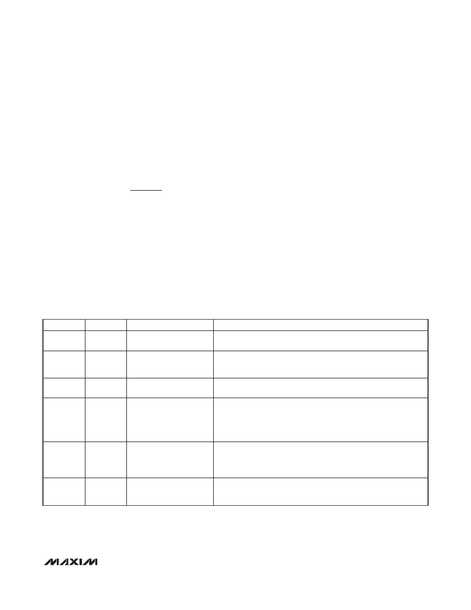
SHDN
SKIP
OPERATING MODE
DESCRIPTION
GND X
DISABLED
Low-Power Shutdown Mode. DL forced low, and the controller is
disabled. The supply current drops to 10µA (max).
Rising X
Pulse-Skipping
1.56mV/µs Slew Rate
Startup. When
SHDN is pulled high, the MAX17409 begins the startup
sequence. The controller enables the PWM controller and ramps the
output voltage up to the selected VID voltage.
High Low
Forced-PWM
12.5mV/µs Slew Rate
Full Power. The no-load output voltage is determined by the selected
VID DAC code (G0–G5, Table 4).
High High
Pulse-Skipping
12.5mV/µs Slew Rate
Suspend Mode. The no-load output voltage is determined by the
selected VID DAC code (G0–G5, Table 4). When SKIP is pulled high,
the MAX17409 immediately enters pulse-skipping operation, allowing
automatic PWM/PFM switchover under light loads. The PWRGD upper
threshold is blanked during the transition.
Falling X
Forced-PWM
1.56mV/µs Slew Rate
Shutdown. When
SHDN is pulled low, the MAX17409 immediately
pulls PWRGD low, and the output voltage is ramped down to ground.
Once the output reaches 0V, the controller enters the low-power
shutdown state.
High X
DISABLED
Fault Mode. The fault latch has been set by the MAX17409 UVP or
thermal-shutdown protection, or by the OVP protection. The controller
remains in fault mode until V
CC
power is cycled or
SHDN toggled.
Table 3. MAX17409 Operating Mode Truth Table