Pin description – Rainbow Electronics MAX17409 User Manual
Page 10
MAX17409
1-Phase Quick-PWM GPU Controller
10
______________________________________________________________________________________
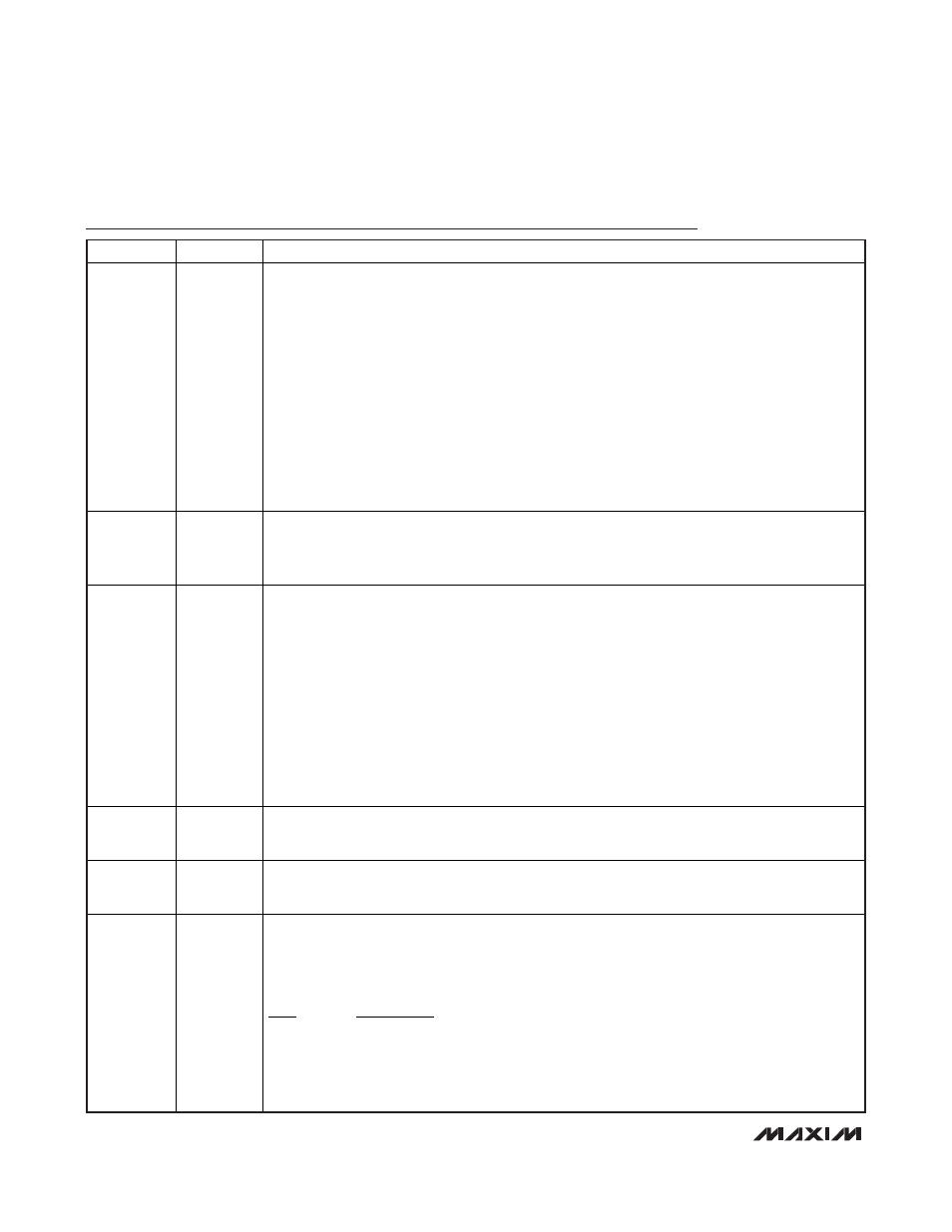
Pin Description
PIN
NAME
FUNCTION
1 IMON
Current Monitor Output. The MAX17409 IMON output sources a current that is directly proportional
to the current-sense voltage as defined by:
I
IMON
= G
m(IMON)
x (V
CSP
- V
CSN
)
where G
m(IMON)
= 5mS (typ).
The IMON current is unidirectional (sources current out of IMON only) for positive current-sense
values. For negative current-sense voltages, the IMON current is zero.
Connect an external resistor between IMON and GNDS to create the desired IMON gain based on
the following equation:
R
IMON
= 1.0V/(I
LOAD(MAX)
x R
SENSE
x G
m(IMON)
)
where I
LOAD(MAX)
is the maximum load current, and R
SENSE
is the current-sense voltage.
The IMON voltage is internally clamped to 1.1V. The transconductance amplifier and voltage
clamp are internally compensated, so IMON cannot drive large external capacitance values. To
filter the IMON signal, use an RC filter as shown in Figure 1.
2 GNDS/OFSP
Remote Ground-Sense Input/Positive Offset Input. Connect directly to the ground-sense pin or
ground connection of the load. GNDS internally connects to a transconductance amplifier that
adjusts the feedback voltage—compensating for voltage drops between the regulator’s ground and
the processor’s ground.
3 FB
Remote-Sense Feedback Input and Voltage-Positioning Transconductance Amplifier Output.
Connect resistor R
FB
between FB and the output remote-sense pin (or Kelvin-sensed to the supply
pin of the load) for best accuracy and to set the steady-state droop based on the voltage-
positioning gain requirement:
R
FB
= R
DROOP
/(R
SENSE
x G
MD
)
where R
DROOP_DC
is the desired voltage-positioning slope, G
MD
= 600µS (typ), and R
SENSE
is the
current-sense resistance with respect to CSP to CSN current-sense inputs. See the Current Sense
section for details on designing with sense resistors or inductor DCR sensing.
Shorting FB directly to the output effectively disables voltage positioning, but impacts the stability
requirements. Designs that disable voltage positioning require a higher minimum output
capacitance ESR to maintain stability (see the Output Capacitor Selection section).
FB enters a high-impedance state in shutdown.
4 CSN
Negative Inductor Current-Sense Input. Connect CSN to the negative terminal of the inductor
current-sensing resistor or directly to the negative terminal of the inductor if the lossless DCR
sensing method is used (see Figure 3).
5 CSP
Positive Inductor Current-Sense Input. Connect CSP to the positive terminal of the inductor current-
sensing resistor or directly to the positive terminal of the filtering capacitor used when the
lossless DCR sensing method is used (see Figure 3).
6 SKIP
Pulse-Skipping Control Input. The SKIP signal indicates the power usage and sets the operating
mode of the MAX17409. When the system forces SKIP high, the MAX17409 immediately enters
automatic pulse-skipping mode. The controller returns to continuous forced-PWM mode when SKIP
is pulled low and the output is in regulation. SKIP determines the operating mode and output-
voltage transition slew rate as shown in the truth table below:
SKIP Functionality
0 Normal slew rate, forced-PWM mode
1 Normal slew rate, skip mode
The SKIP state is ignored during soft-start and shutdown. The MAX17409 always uses pulse-
skipping mode during startup to ensure a monotonic power-up. During shutdown, the controller
always uses forced-PWM mode so the output can be actively discharged.