Rf02, Ac characteristic – Rainbow Electronics RF02 User Manual
Page 7
RF02
Tel: +86-755-86096587 Fax: +86-755-86096602 E-mail: [email protected] http://www.hoperf.com
V
lba
Low battery detection accuracy
75
mV
V
lb
Low battery detector threshold
Programmable in
0.1 V steps
2.2
5.3
V
V
il
Digital input low level
0.3*V
dd
V
V
ih
Digital input high level
0.7*V
dd
V
I
il
Digital input current
V
il
= 0 V
-1
1
µA
I
ih
Digital input current
V
ih
= V
dd
, V
dd
= 5.4
V
-1
1
µA
V
ol
Digital output low level
I
ol
= 2 mA
0.4
V
V
oh
Digital output high level
I
oh
= -2 mA
V
dd
-0.4
V
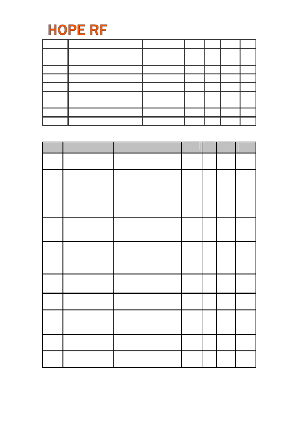
AC Characteristic
Symbol
Parameter
Conditions/Notes
Min
Typ
Max
Units
f
ref
PLL reference
frequency
Crystal operation mode is
parallel (Note 2)
9 10 11
MHz
f
o
433MHz band, 2.5kHz
resolution
868MHz band, 5.0kHz
resolution
915MHz band, 7.5kHz
resolution
430.24
860.48
900.72
439.75
879.51
929.27
MHz
t
lock
PLL lock time
Frequency error < 10 kHz after
10 MHz step, POR default PLL
setting(Note 7)
20
µs
t
sp
PLL startup time
After turning on from idle
mode, with crystal oscillator
already stable, POR default
PLL setting (Note 7)
250
µs
I
OUT
Open collector output
current (Note 3)
At all bands
0.5 6
mA
P
maxL
Available output power
(433MHz band)
With opt. antenna impedance
(Note 4)
8
dBm
P
maxH
Available output power
(868 and 915 MHz
band)
With opt. antenna impedance
(Note 4)
6
dBm
P
out
Typical output power
Selectable in 3 dB steps (Note
3)
P
max
-21
P
max
dBm
P
sp
Spurious emission
At max power with loop
antenna (Note 5)
-50
dBc