Rf02, Timing diagram, Control commands – Rainbow Electronics RF02 User Manual
Page 11
RF02
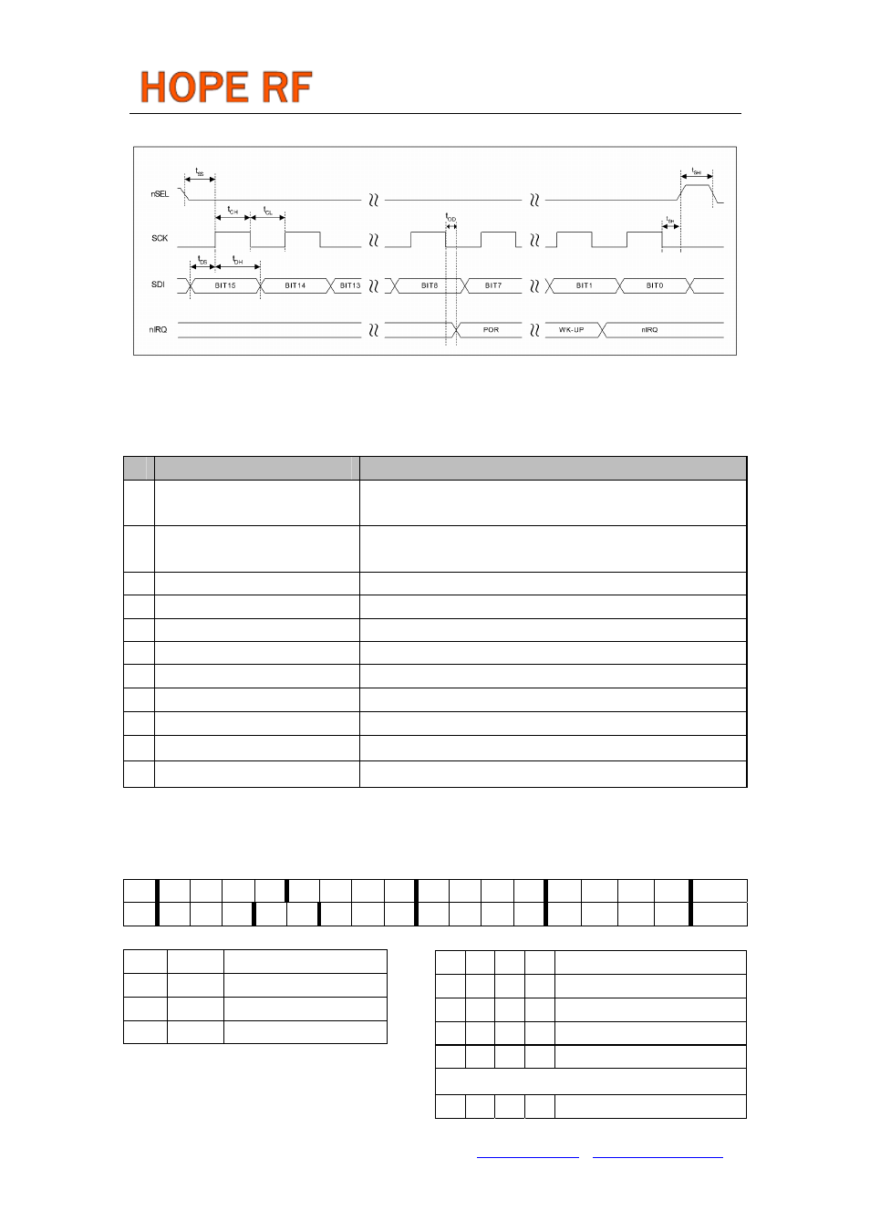
Timing Diagram
Control Commands
Control Command
Related Parameters/Functions
1 Configuration Setting Command
Frequency band, microcontroller clock output, crystal load
capacitance, frequency deviation
2 Power Management Command
Crystal oscillator, synthesizer, power amplifier, low battery
detector, wake-up timer, clock output buffer
3 Frequency Setting Command
Carrier frequency
4
Data Rate Command
Bit rate
5 Power Setting Command
Nominal output power, OOK mode
6 Low Battery Detector Command Low battery threshold limit
7 Sleep Command
Length of the clock tail after power down
8 Wake-Up Timer Command
Wake-up time period
9 Data Transmit Command
Data transmission
10 Status Register Command
Transmitter status read
11 PLL Setting Command
PLL bandwidth can be modified by this command
Note:
In the following tables the POR column shows the default values of the command registers after
power-on.
1. Configuration Setting Command
bit 15 14 13 12 11 10 9 8 7 6 5 4 3 2 1 0 POR
1 0 0 b1
b0
d2
d1
d0
x3
x2
x1
x0
ms
m2
m1
m0
8080h
b1
b0
Frequency Band [MHz]
0 1 433
1 0 868
1 1 915
x3
x2
x1
x0
Crystal Load Capacitance [pF]
0 0 0 0 8.5
0 0 0 1 9.0
0 0 1 0 9.5
0 0 1 1 10.0
…… ……
1 1 1 0 15.5
1 1 1 1 16.0
Tel: +86-755-86096587 Fax: +86-755-86096602 E-mail: [email protected] http://www.hoperf.com