Rf02 – Rainbow Electronics RF02 User Manual
Page 14
RF02
5. Power Setting Command
bit 7 6 5 4 3
2 1
0
POR
1 0 1 1 0
p2 p1 p0 B0h
2
p1
p0
Output Power [dB]
0
0
0
0
0
0
1
-3
0
1
0
-6
0
1
1
-9
1
0
0
-12
1
0
1
-15
1
1
0
-18
1
1
1
-21
The output power is given in the table
as relative to the maximum available
power, which depends on the actual
antenna impedance.
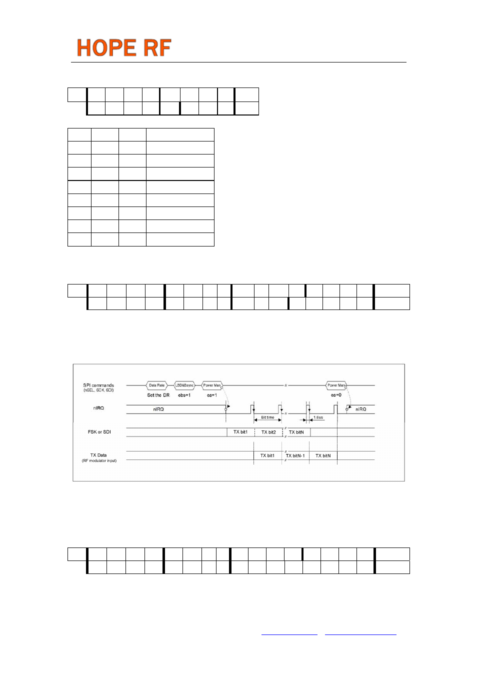
6. Low Battery Detector and TX Bit Synchronization Command
bit 15 14 13 12 11 10 9
8
7 6
5 4 3 2 1 0 POR
1 1 0 0 0 0 1
0
dwc
0
ebs
t4
t3
t2
t1
t0
C200h
Bit 7
Bit 5
Command.5
The 5-bit value T of
lb
of the detector:
V
lb
= 2.2 V + T * 0.1 V
7. Sleep Command
bit 15 14 13 12 11 10 9
8
7 6 5 4 3 2 1 0 POR
1 1 0 0 0 1 0
0
s7
s6
s5
s4
s3
s2
s1
s0
C400h
The effect of this command depends on the Power Management Command. It immediately disables the
power amplifier (if a0=1 and ea=0) and the synthesizer (if a1=1 and es=0). Stops the crystal oscillator
Tel: +86-755-86096587 Fax: +86-755-86096602 E-mail: [email protected] http://www.hoperf.com