Rf02 – Rainbow Electronics RF02 User Manual
Page 16
RF02
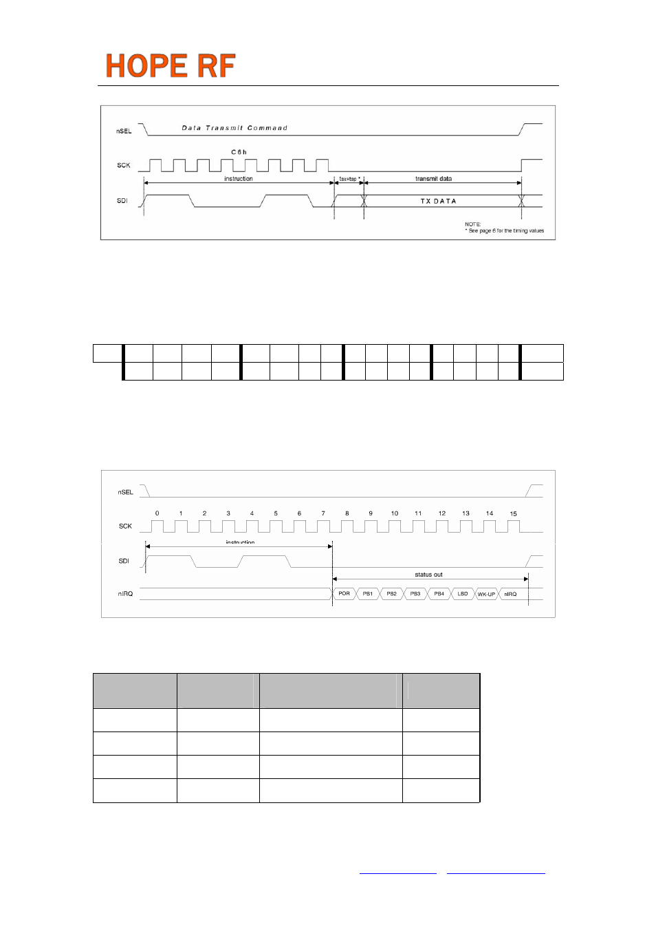
Data Transmit Sequence Through the SDI Pin
Note:
Do not send CLK pulses with the TX data bits, otherwise they will be interpreted as commands.
This mode is not SPI compatible.
If the crystal oscillator and the PLL are running, the t
sx
+t
sp
delay is not needed.
10 . Status Register Read Command
bit
15
14
13
12
11
10
9
8
7
6
5
4
3
2
1
0
POR
1
1
0
0
1
1
0
0
0
0
0
0
0
0 0 0
--
With this command, it is possible to read the chip’s status register through the nIRQ pin. This command
clears the last serviced interrupt and processing the next pending one will start (if there is any).
Status Register Read Sequence
11. PLL Setting Command
PLL bandwidth can be selected by this command
PLL command
Max data rate
[kbps]
Phase noise at 1MHz offset
[dbc/Hz]
Comments
D240h 19.2 -112
25%current
D2C0h 38.4 -110
33%current
D200h 68.9 -107
50%current
D280h 115.2 -102
100%current
Tel: +86-755-86096587 Fax: +86-755-86096602 E-mail: [email protected] http://www.hoperf.com