Control interface, Rf02, Other important characteristics – Rainbow Electronics RF02 User Manual
Page 10: Timing specification
RF02
Other Important Characteristics
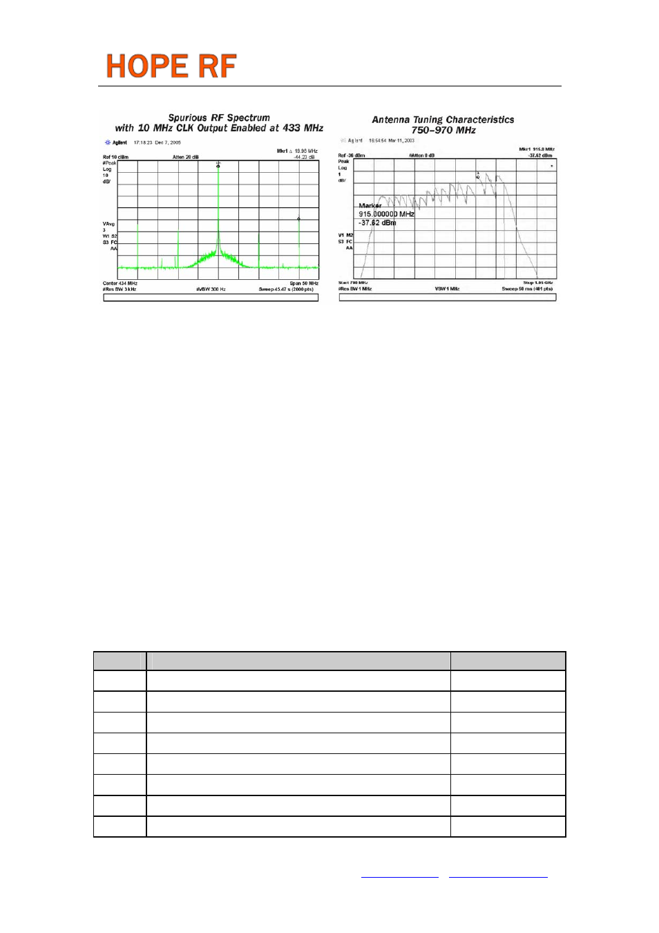
The antenna tuning characteristics was recorded in “max-hold” state of the spectrum analyzer. During the
measurement, the transmitters were forced to change frequencies by forcing an external reference signal
to the XTL pin. While the carrier was changing the antenna tuning circuit switched trough all the available
states of the tuning circuit. The graph clearly demonstrates that while the complete output circuit had
about a 40 MHz bandwidth, the tuning allows operating in a 220 MHz band. In other words the tuning
circuit can compensate for 25% variation in the resonant frequency due to any process or manufacturing
spread.
CONTROL INTERFACE
Commands to the transmitters are sent serially. Data bits on pin SDI are shifted into the device upon the
rising edge of the clock on pin SCK whenever the chip select pin nSEL is low. When the nSEL signal is
high, it initializes the serial interface. The number of bits sent is an integer multiple of 8. All commands
consist of a command code, followed by a varying number of parameter or data bits. All data are sent
MSB first (e.g. bit 15 for a 16-bit command). Bits having no influence (don’t care) are indicated with X.
The Power On Reset (POR) circuit sets default values in all control and command registers.
Timing Specification
Symbol Parameter
Minimum Value [ns]
t
CH
Clock high time
25
t
CL
Clock low time
25
t
SS
Select setup time (nSEL falling edge to SCK rising edge)
10
t
SH
Select hold time (SCK falling edge to nSEL rising edge)
10
t
SHI
Select high time
25
t
DS
Data setup time (SDI transition to SCK rising edge)
5
t
DH
Data hold time (SCK rising edge to SDI transition)
5
t
OD
Data delay time
10
Tel: +86-755-86096587 Fax: +86-755-86096602 E-mail: [email protected] http://www.hoperf.com