Rf02, Oscillator control logic – Rainbow Electronics RF02 User Manual
Page 13
RF02
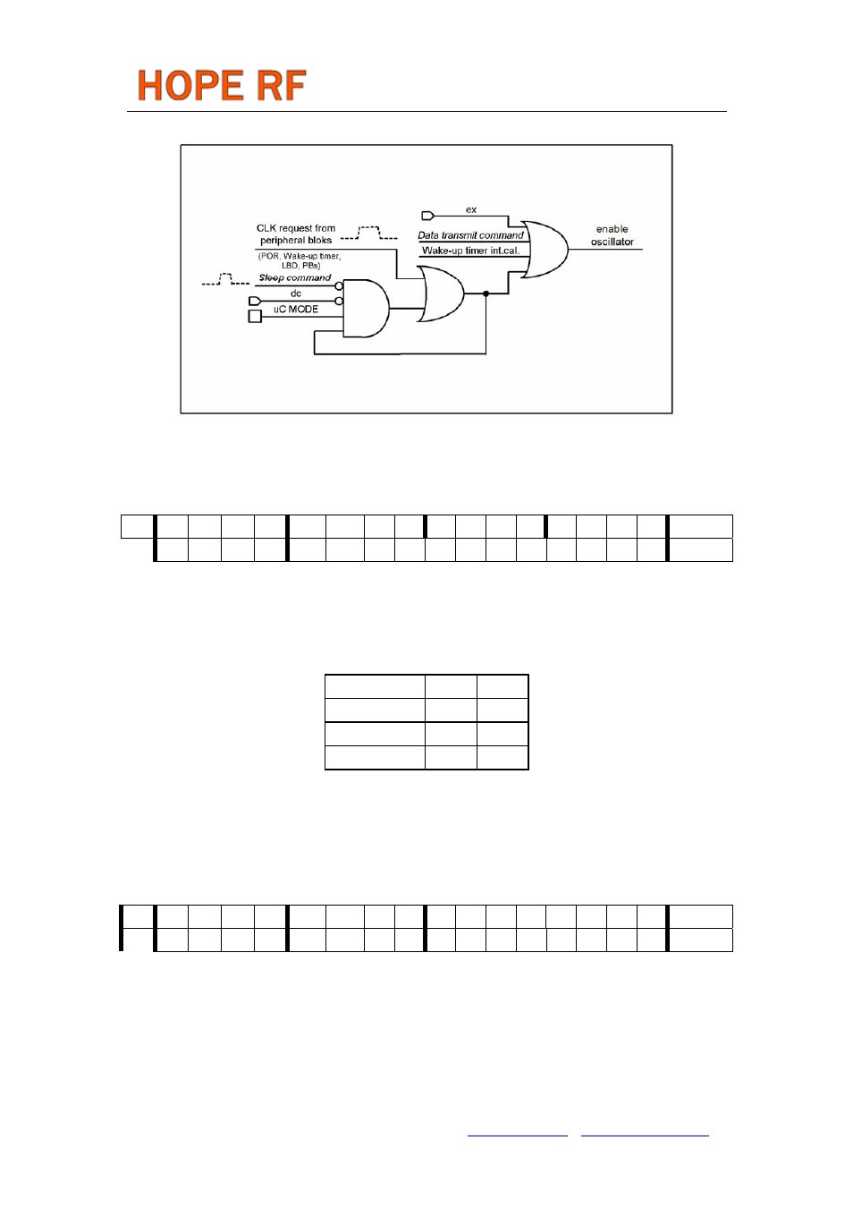
Oscillator control logic
3. Frequency Setting Command
bit 15 14 13 12 11 10 9 8 7 6 5 4 3 2 1 0 POR
1 0 1 0 f11
f10
f9
f8
f7
f6
f5
f4
f3
f2
f1
f0
A7D0h
The 12-bit parameter of the Frequency Setting Command
be in the range of 96 and 3903. When F is out of range, the previous value is kept. The synthesizer
center frequency f
0
can be calculated as:
f
0
= 10 MHz * C1 * (C2 + F/4000)
The constants C1 and C2 are determined by the selected band as:
Band [MHz]
C1
C2
433
1
43
868
2
43
915
3
30
Note:
• For correct operation of the frequency synthesizer, the frequency and band of operation need to be
programmed before the synthesizer is started. Directly after activation of the synthesizer, the RF VCO is
calibrated to ensure proper operation in the programmed frequency band.
4. Data Rate Command
bit 15 14 13 12 11 10 9 8 7 6 5 4 3 2 1 0 POR
1 1 0 0 1 0 0 0 r7
r6
r5
r4
r3
r2
r1
r0
C800h
The transmitted bit rate is determined by the 8-bit value R (bits <r7 : r0>) as:
BR = 10 MHz / 29 / (R+1)
Apart from setting custom values, the standard bit rates from 2.4 to 115.2 kbps can be approximated with
minimal error.
Note:
• PLL bandwidth should be set according the data rate. Please see the PLL Setting Command.
Tel: +86-755-86096587 Fax: +86-755-86096602 E-mail: [email protected] http://www.hoperf.com