Rf02 – Rainbow Electronics RF02 User Manual
Page 15
RF02
after S periods of the microcontroller clock (if a1=1 and ex=0) to enable the microcontroller to execute all
necessary commands before entering sleep mode itself. The 8-bit value S is determined by bits
8. Wake-Up Timer Command
bit
15
14
13
12
11
10
9
8
7 6 5 4 3 2 1 0 POR
1 1 1 r4 r3 r2 r1
r0
m7
m6
m5
m4
m3
m2
m1
m0
E000h
The wake-up time period can be calculated as:
T
wake-up
= M * 2
R
[ms],
where M is defined by the
Note:
•
For continual operation the et bit should be cleared and set at the end of every cycle.
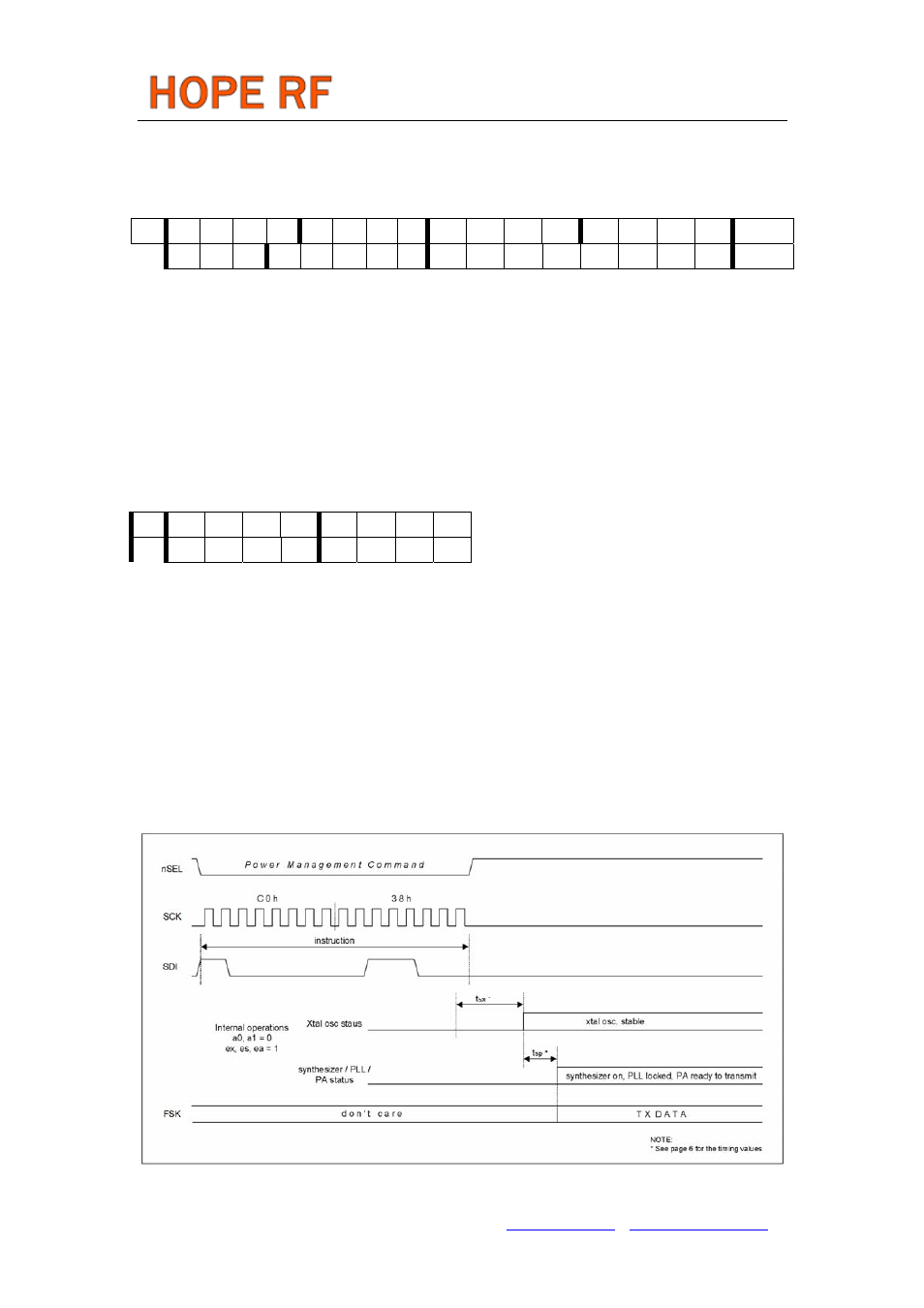
9. Data Transmit Command
bit
7 6 5 4 3 2 1 0
1 1 0 0 0 1 1 0
This Command Indicates that the following bitstream coming in via the serial interface is to be
transmitted.
Note
• This command is not needed if the transmitters’ power management bits (ex, es and ea) are fully
controlled by the microcontroller and TX data comes through the FSK pin.
• If the crystal oscillator was formerly switched off (ex=0), the internal oscillator needs t
sx
time, to
switch on. The actual value depends on the type of quartz crystal used.
• If the synthesizer was formerly switched off (es=0), the internal PLL needs t
sp
startup time. Valid data
can be transmitted only when the internal locking process is finished.
Data Transmit Sequence Through the FSK Pin
Tel: +86-755-86096587 Fax: +86-755-86096602 E-mail: [email protected] http://www.hoperf.com