Rf12, Data filtering and clock recovery, Data validity blocks – Rainbow Electronics RF12 User Manual
Page 4
RF12
Data Filtering and Clock Recovery
Output data filtering can be completed by an external capacitor or by using digital filtering according
to the final application.
Analog operation: The filter is an RC type low-pass filter followed by a Schmitt-trigger (St). The
resistor (10 kOhm) and the St are integrated on the chip. An (external) capacitor can be chosen
according to the actual bit rate. In this mode, the receiver can handle up to 256 kbps data rate. The FIFO
can not be used in this mode and clock is not provided for the demodulated data.
Digital operation: A digital filter is used with a clock frequency at 29 times the bit rate. In this mode
there is a clock recovery circuit (CR), which can provide synchronized clock to the data. Using this clock
the received data can fill a FIFO. The CR has three operation modes: fast, slow, and automatic. In slow
mode, its noise immunity is very high, but it has slower settling time and requires more accurate data
timing than in fast mode. In automatic mode the CR automatically changes between fast and slow mode.
The CR starts in fast mode, then after locking it automatically switches to slow mode (Only the digital data
filter and the clock recovery use the bit rate clock. For analog operation, there is no need for setting the
correct bit rate.)
Data Validity Blocks
RSSI
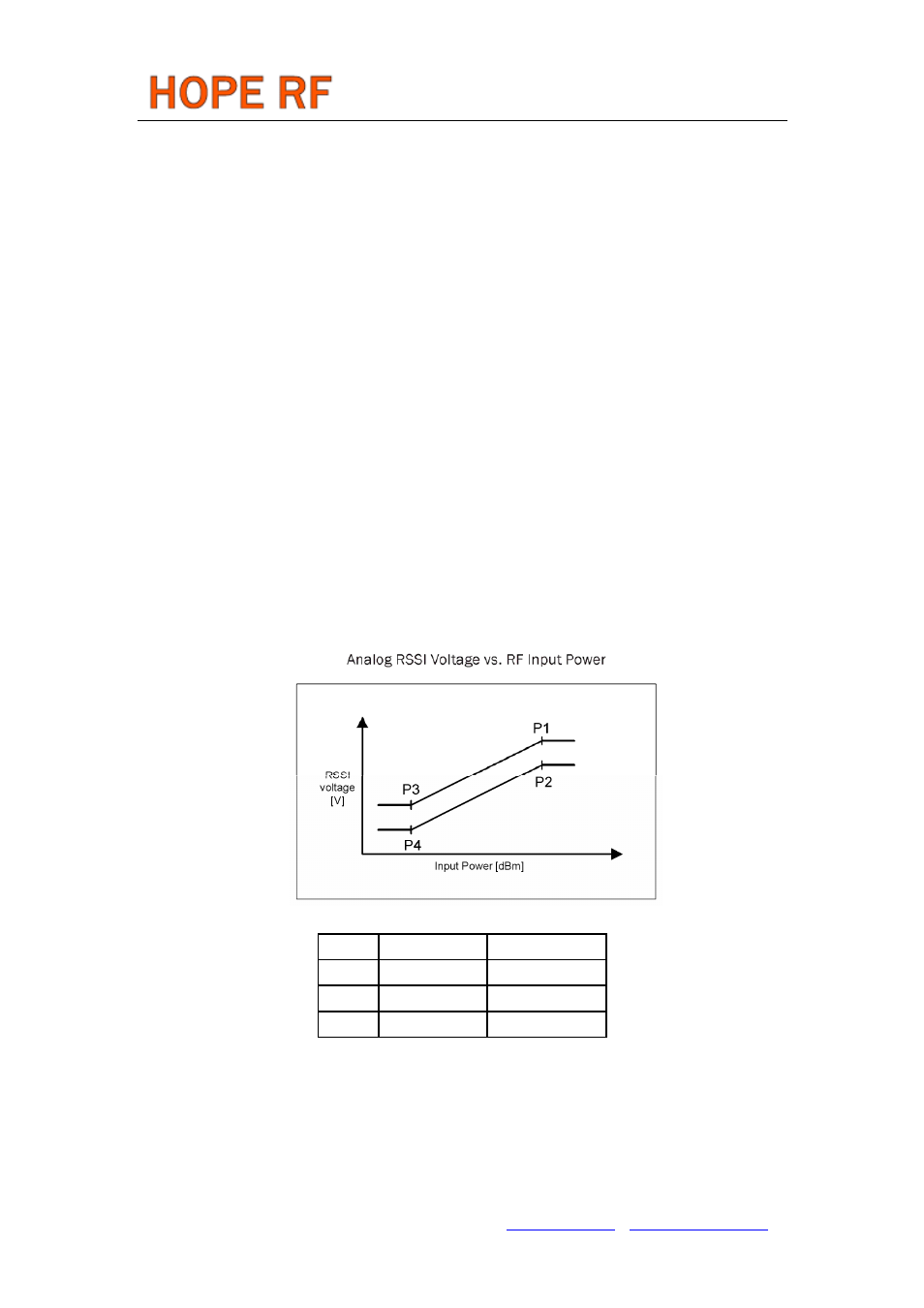
A digital RSSI output is provided to monitor the input signal level. It goes high if the received signal
strength exceeds a given preprogrammed level. An analog RSSI signal is also available. The RSSI
settling time depends on the external filter capacitor. Pin 19 is used as analog RSSI output. The digital
RSSI can be monitored by reading the status register.
P1
-65 dBm
1300 mV
P2
-65 dBm
1000 mV
P3
-100 dBm
600 mV
P4
-100 dBm
300 mV
DQD
The Data Quality Detector is based on counting the spikes on the unfiltered received data. For
correct operation, the “DQD threshold” parameter must be filled in by using the Data Filter Command.
AFC
By using an integrated Automatic Frequency Control (AFC) feature, the receiver can minimize the
TX/RX offset in discrete steps, allowing the use of:
Tel: +86-755-86096587 Fax: +86-755-86096602 E-mail: [email protected] http://www.hoperf.com