Detailed feature-level description, Rf12, Rf power amplifier (pa) – Rainbow Electronics RF12 User Manual
Page 3: Baseband filters
RF12
DETAILED FEATURE-LEVEL DESCRIPTION
The RF12 FSK transceiver is designed to cover the unlicensed frequency bands at 315, 433, 868
and 915 MHz. The devices facilitate compliance with FCC and ETSI requirements.
The receiver block employs the Zero-IF approach with I/Q demodulation, allowing the use of a
minimal number of external components in a typical application. The RF12 incorporates a fully integrated
multi-band PLL synthesizer, PA with antenna tuning, an LNA with switch-able gain, I/Q down converter
mixers, baseband filters and amplifiers, and an I/Q demodulator followed by a data filter.
PLL
The programmable PLL synthesizer determines the operating frequency, while preserving accuracy
based on the on-chip crystal-controlled reference oscillator. The PLL’s high resolution allows the usage of
multiple channels in any of the bands.
The RF VCO in the PLL performs automatic calibration, which requires only a few microseconds.
Calibration always occurs when the synthesizer starts. If temperature or supply voltage changes
significantly, VCO recalibration can be invoked easily. Recalibration can be initiated at any time by
switching the synthesizer off and back on again.
RF Power Amplifier (PA)
The power amplifier has an open-collector differential output and can directly drive a loop antenna
with a programmable output power level. An automatic antenna tuning circuit is built in to avoid costly
trimming procedures and the so-called “hand effect.”
LNA
The LNA has 250 Ohm input impedance, which functions well with the proposed antennas. If the
RF input of the chip is connected to 50 Ohm devices, an external matching circuit is required to provide
the correct matching and to minimize the noise figure of the receiver.
The LNA gain can be selected (0, –6, –14, –20 dB relative to the highest gain) according to RF signal
strength. It can be useful in an environment with strong interferers.
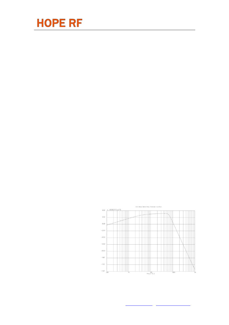
Baseband Filters
Tel: +86-755-86096587 Fax: +86-755-86096602 E-mail: [email protected] http://www.hoperf.com
electable
BW) of
The receiver bandwidth is s
by programming the bandwidth (
the baseband filters. This allows setting
up the receiver according to the
characteristics of the signal to be
received.
An appropriate bandwidth can be
chosen to accommodate various FSK
deviation, data rate and crystal tolerance
requirements. The filter structure is 7th
order Butterworth low-pass with 40 dB
suppression at 2*BW frequency. Offset cancellation is done by using a high-pass filter with a cut-off
frequency below 7 kHz.