Rf12, Ac characteristics (receiver), Ac characteristics (transmitter) – Rainbow Electronics RF12 User Manual
Page 10
RF12
Tel: +86-755-86096587 Fax: +86-755-86096602 E-mail: [email protected] http://www.hoperf.com
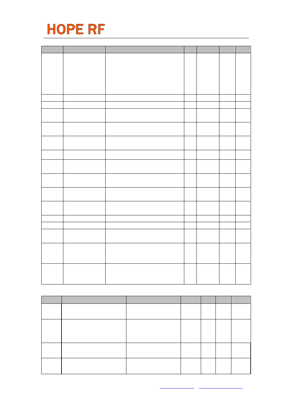
AC Characteristics (Receiver)
Symbol
Parameter
Conditions/Notes
Min Typ
Max Units
BW
Receiver
bandwidth
mode 0
mode 1
mode 2
mode 3
mode 4
mode 5
60
120
180
240
300
360
67
134
200
270
350
400
75
150
225
300
375
450
kHz
BR
FSK bit rate
With internal digital filters
0.6
115.2 kbps
BRA
FSK bit rate
With analog filter
256
kbps
P
min
Receiver
Sensitivity
BER 10
-3
, BW=67kHz, BR=1.2kbps
(Note 2)
-109 -100
dBm
AFC
range
AFC locking range df
FSK
: FSK deviation in the received
signal
0.8*df
FSK
IIP3
inh
Input IP3
In band interferers in high bands(868,
915 MHz)
-21
dBm
IIP3
outh
Input IP3
Out of band interferers l f-f
o
l > 4 MHz
-18
dBm
IIP3
inl
IIP3 (LNA –6 dB
gain)
In band interferers in low bands (315,
433 MHz)
-15
dBm
IIP3
outl
IIP3 (LNA –6 dB
gain)
Out of band interferers l f-f
o
l > 4 MHz
-12
dBm
P
max
Maximum input
power
LNA: high gain
0
dBm
C
in
RF input
capacitance
1
pF
RS
a
RSSI accuracy
+/-5
dB
RS
r
RSSI range
46
dB
C
ARSSI
Filter capacitor for
ARSSI
1
nF
RS
step
RSSI
programmable
level steps
6
dB
RS
resp
DRSSI response
time
Until the RSSI signal goes high after
the input signal exceeds the
preprogrammed limit C
ARRSI
= 5 nF
500
us
AC Characteristics (Transmitter)
Symbol Parameter
Conditions/Notes
Min
Typ Max Units
I
OUT
Open collector output DC
current
Programmable
0.5
6
mA
P
max
Available output power with
optimal antenna impedance
(Note 3, 4)
In low bands
In high bands
8
4
dBm
P
out
Typical output power
Selectable in 3 dB steps
(Note 5)
P
max
-21
P
max
dBm
P
sp
Spurious emission
At max power with loop
antenna (Note 6)
-50 dBc