Rf12 – Rainbow Electronics RF12 User Manual
Page 22
RF12
12. Wake-Up Timer Command
bit 15 14 13 12 11 10 9 8
7 6 5 4 3 2 1 0 POR
1 1 1 r4 r3 r2 r1
r0
m7
m6
m5
m4
m3
m2
m1
m0 E196h
The wake-up time period can be calculated by (m7 to m0) and (r4 to r0):
T
wake-up
= M * 2
R
[ms]
Note:
•
For continual operation the et bit should be cleared and set at the end of every cycle.
•
For future compatibility, use R in a range of 0 and 29.
13. Low Duty-Cycle Command
bit
15
14 13 12 11
10 9
8
7 6 5 4 3 2 1 0 POR
1 1 0 0 1 0 0
r0
d6
d5
d4
d3
d2
d1
d0 en C80Eh
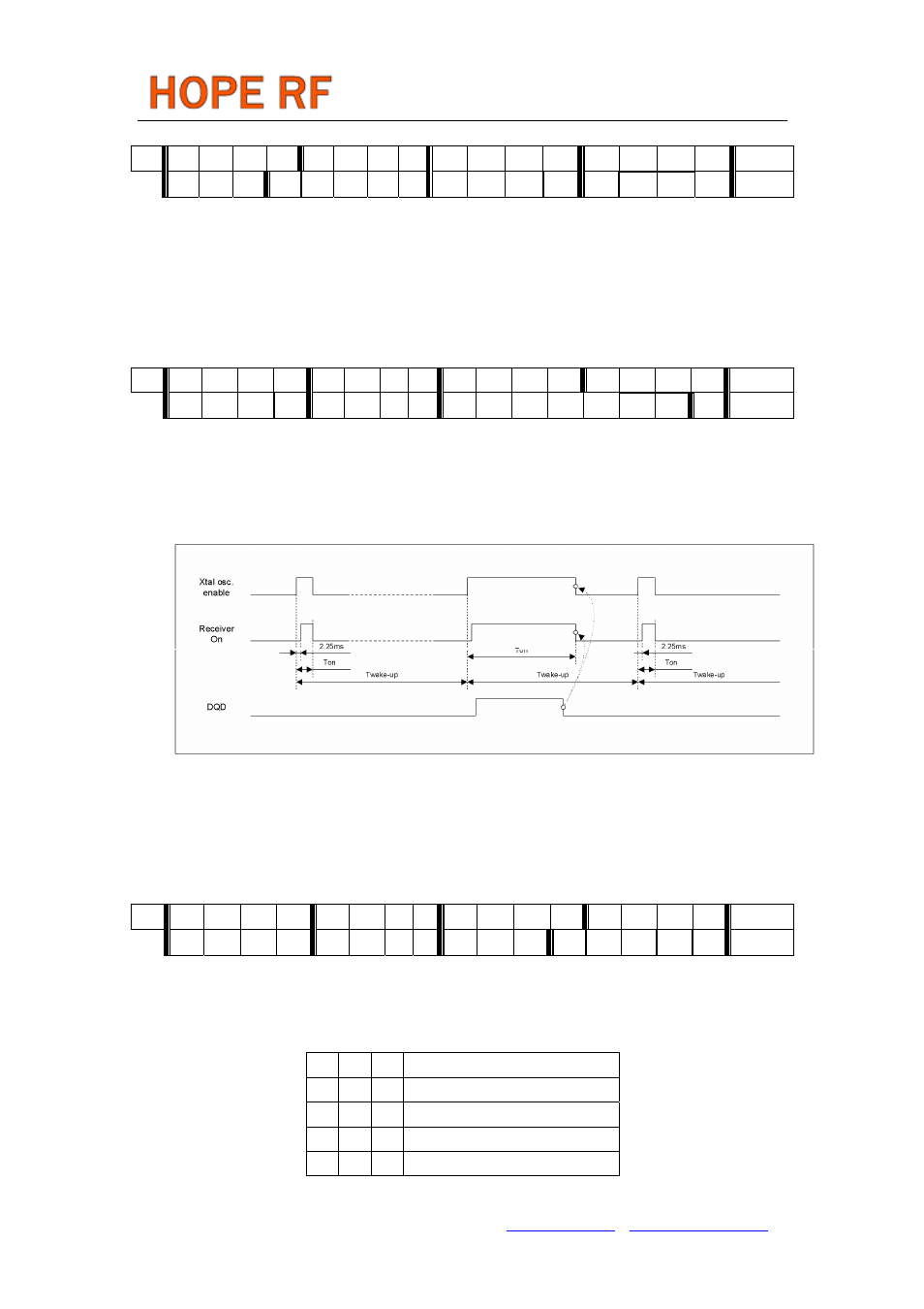
With this command, Low Duty-Cycle operation can be set in order to decrease the average power
consumption in receiver mode. The time cycle is determined by the Wake-Up Timer Command. The
Duty-Cycle can be calculated by using (d6 to d0) and M. (M is parameter in a Wake-Up Timer
Command.)
Duty-Cycle= (D * 2 +1) / M *100%
Bit 0 (en): Enables the Low Duty-Cycle Mode. Wake-up timer interrupt not generated in this mode.
Note:
In this operation mode, bit er must be cleared and bit ew must be set in the Power Management
Command.
14. Low Battery Detector and Microcontroller Clock Divider Command
bit 15 14 13 12 11 10 9
8
7 6 5 4 3 2 1 0 POR
1 1 0 0 0 0 0
0
d2
d1
d0
v4
v3
v2
v1
v0
C000h
The 5 bit parameter (v4 to v0) represents the value V, which defines the threshold voltage V
lb
of the
detector:
V
lb
= 2.2 + V * 0.1 [V]
Clock divider configuration:
d2 d1 d0
Clock Output Frequency [ M Hz]
0 0 0
1
0 0 1
1.25
0 1 0
1.66
0 1 1
2
Tel: +86-755-86096587 Fax: +86-755-86096602 E-mail: [email protected] http://www.hoperf.com