U3742bm, Configuration of the receiver – Rainbow Electronics U3742BM User Manual
Page 19
19
U3742BM
4735A–RKE–11/03
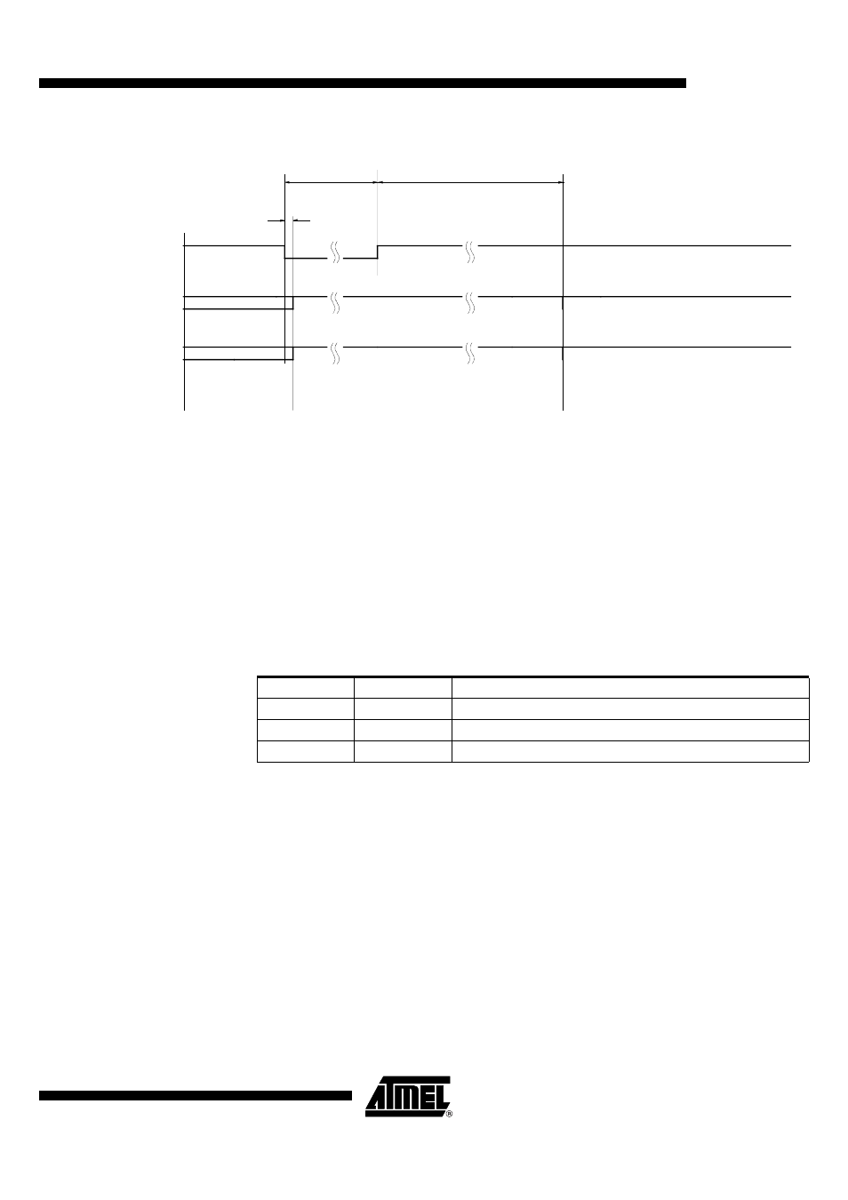
Figure 22. Timing Diagram of the OFF-command via Pin ENABLE
Configuration of the
Receiver
The U3742BM receiver is configured via two 12-bit RAM registers called OPMODE and
LIMIT. The registers can be programmed by means of the bi-directional DATA port. If
the register contents have changed due to a voltage drop, this condition is indicated by a
certain output pattern called reset marker (RM). The receiver must be reprogrammed in
that case. After a power-on reset (POR), the registers are set to default mode. If the
receiver is operated in default mode, there is no need to program the registers.
Table 3 on page 20 shows the structure of the registers. According to Table 2, bit 1
defines if the receiver is set back to polling mode via the OFF command, (see section
“Receiving Mode” on page 16) or if it is programmed. Bit 2 represents the register
address. It selects the appropriate register to be programmed.
Table 4 on page 20 and the following illustrate the effect of the individual configuration
words. The default configuration is highlighted for each word.
BR_Range sets the appropriate baud rate range. At the same time it defines XLim. XLim
is used to define the bit check limits T
Lim_min
and T
Lim_max
as shown in Table 4 on page
20.
ENABLE
DATA (U3742BM)
Serial bi-directional
data line
X
X
t
off
Receiving mode
Startup mode
T
Sleep
T
Doze
Table 2. Effect of Bit 1 and Bit 2 in Programming the Registers
Bit 1
Bit 2
Action
1
x
The receiver is set back to polling mode (OFF command)
0
1
The OPMODE register is programmed
0
0
The LIMIT register is programmed