U3742bm – Rainbow Electronics U3742BM User Manual
Page 18
18
U3742BM
4735A–RKE–11/03
After the end of data transmission, the receiver remains active and random noise pulses
appear at pin DATA. The edge-to-edge time period t
ee
of the majority of these noise
pulses is equal to or slightly higher than T
DATA_min
.
Switching the Receiver Back
to Sleep Mode
The receiver can be set back to polling mode via pin DATA or via pin ENABLE.
When using pin DATA, this pin must be pulled to Low for the period t
1
by the connected
microcontroller. Figure 21 illustrates the timing of the OFF command (see also Figure 25
on page 23). The minimum value of t
1
depends on BR_Range. The maximum value for
t
1
is not limited but it is recommended not to exceed the specified value to prevent eras-
ing the reset marker. This item is explained in more detail in the section “Configuration
of the Receiver” on page 19. Setting the receiver to sleep mode via DATA is achieved
by programming bit 1 of the OPMODE register to be '1'. Only one sync pulse (t
3
) is
issued.
The duration of the OFF command is determined by the sum of t
1
, t
2
and t
10
. After the
OFF command, the sleep time T
Sleep
elapses. Note that the capacitive load at pin DATA
is limited. The resulting time constant
t
together with an optional external pull-up resistor
may not be exceeded to ensure proper operation.
If the receiver is set to polling mode via pin ENABLE, an 'L' pulse (T
Doze
) must be issued
at that pin. Figure 22 on page 19 illustrates the timing of that command. After the posi-
tive edge of this pulse, the sleep time T
Sleep
elapses. The receiver remains in sleep
mode as long as ENABLE is held to 'L'. If the receiver is polled exclusively by a micro-
controller, T
Sleep
can be programmed to 0 to enable a instantaneous response time. This
command is the faster option than via pin DATA at the cost of an additional connection
to the microcontroller.
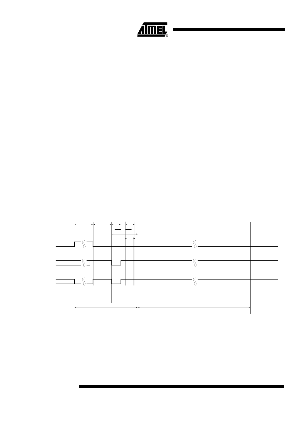
Figure 21. Timing Diagram of the OFF-command via Pin DATA
Out1 (microcontroller)
DATA (U3742BM)
Serial bi-directional
data line
X
Bit 1
("1")
X
t
1
t
2
t
3
t
4
t
5
t
7
(Startbit)
Startup mode
OFF command
T
Sleep
Receiving
mode
t
10