Sidedraw instructions (continued), Accessory instructions – Grain Systems Tanks PNEG-1000 User Manual
Page 90
13. Accessory Instructions
90
PNEG-1000 2.66" Commercial Tank Stiffener and Sidewall
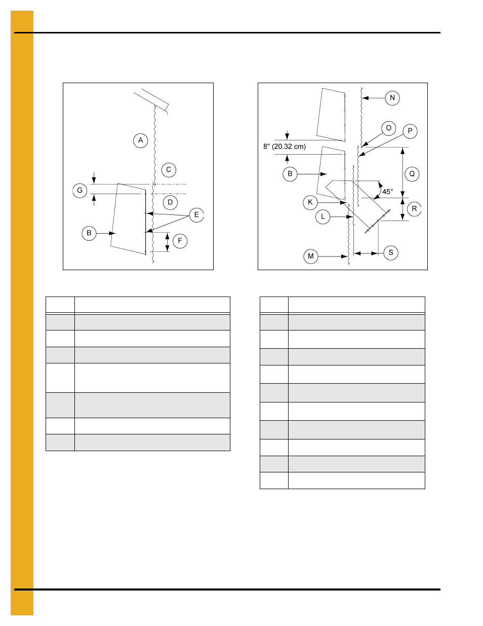
Sidedraw Instructions (Continued)
2.66" Sidedraw Instructions - 2 and 3 Post (Externally Stiffened) (Continued)
Figure 13F Externally Stiffened
Figure 13G Externally Stiffened
NOTE: Unload tubes and supports from rack and pinion not provided by GSI.
NOTE: When installing the discharge weldment, use the same 3/8" bolts as the installation rings vertical
seam. For example, if 3/8" x 1-1/2" bolts were used, utilize that size bolt.
Ref #
Description
A
Inside of bin
B
Chute
C
First Horizontal Seam from Eave
D
Starting Location: 2
nd
Inside Corrugation
of the 2
nd
Ring
E
Field Drill Sidewall to Match Chute
(7/16" Diameter Holes)
F
8" Typical (20.32 cm)
G
2.677" Typical (6.77 cm)
Ref #
Description
B
Chute
K
6
th
Horizontal Seam from Tank Base
L
Sidedraw Plate
M
6
th
Ring from Tank Base
N
8
th
Ring from Tank Base
O
7
th
Horizontal Seam from Tank Base
P
7
th
Ring from Tank Base
Q
26.667" Typical (67.73 cm)
R
16.333" Typical (41.49 cm)
S
12-3/4" Typical (32.39 cm)
- Bin Accessories PNEG-1883 (26 pages)
- Bin Accessories PNEG-104 (2 pages)
- Bin Accessories PNEG-1859 (90 pages)
- Tanks PNEG-4075 (168 pages)
- Bin Accessories PNEG-1789 (7 pages)
- Special Roofs PNEG-1845 (28 pages)
- Unload Augers PNEG-1550 (22 pages)
- Bucket Elevtors, Conveyors, Series II Sweeps PNEG-1842 (114 pages)
- Tanks PNEG-1784 (5 pages)
- Bin Accessories PNEG-1336D (34 pages)
- Bucket Elevtors, Conveyors, Series II Sweeps PNEG-1618 (10 pages)
- Tanks PNEG-4072G (162 pages)
- Unload Augers PNEG-1556 (58 pages)
- Bin Accessories PNEG-268 (2 pages)
- Bin Flooring PNEG-1830 (44 pages)
- Tanks PNEG-603 (56 pages)
- Bin Flooring PNEG-1835 (48 pages)
- Bin Flooring PNEG-1816 (42 pages)
- Bin Accessories PNEG-1870 (28 pages)
- Bin Accessories PNEG-1088 (30 pages)
- Tanks PNEG-1880 (30 pages)
- Tanks PNEG-4054G (168 pages)
- Unload Augers PNEG-1583 (28 pages)
- Bin Accessories PNEG-318 (180 pages)
- Bucket Elevtors, Conveyors, Series II Sweeps PNEG-970 (36 pages)
- Bin Flooring PNEG-219 (32 pages)
- Tanks PNEG-083 (28 pages)
- Bin Flooring PNEG-1826 (42 pages)
- Bin Accessories PNEG-1802 (50 pages)
- Unload Augers PNEG-1521 (64 pages)
- Tanks PNEG-4090A (166 pages)
- Bin Accessories PNEG-1933 (2 pages)
- Bin Accessories PNEG-1496 (2 pages)
- Bucket Elevtors, Conveyors, Series II Sweeps PNEG-1902 (7 pages)
- Bin Accessories PNEG-1177 (16 pages)
- Bucket Elevtors, Conveyors, Series II Sweeps PNEG-1204 (59 pages)
- Bin Accessories PNEG-130 (2 pages)
- Bin Accessories PNEG-1451 (102 pages)
- Tanks PNEG-1095 (76 pages)
- Bin Accessories PNEG-1868 (26 pages)
- Bin Accessories PNEG-1840 (32 pages)
- Unload Augers PNEG-790 (18 pages)
- Tanks PNEG-1461 (124 pages)
- Bin Accessories PNEG-1884 (26 pages)
- Bin Accessories PNEG-1852 (26 pages)