Own in, Figure 13d, Sidedraw instructions (continued) – Grain Systems Tanks PNEG-1000 User Manual
Page 88: Accessory instructions
13. Accessory Instructions
88
PNEG-1000 2.66" Commercial Tank Stiffener and Sidewall
Sidedraw Instructions (Continued)
2.66" Sidedraw Instructions - 2 and 3 Post (Internally Stiffened)
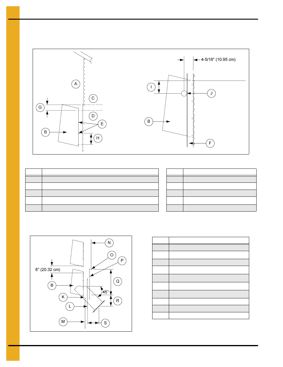
Figure 13C
Field cutting of chutes is necessary to install the wind rings. Locate wind rings as shown. The wind ring
must be assembled into a complete ring and penetrate through the chute. Field drill stiffeners for
attachment brackets (if required).
Figure 13D
NOTE: Unload tubes and supports from rack and
pinion not provided by GSI.
Ref #
Description
Ref #
Description
A
Inside of bin
F
Stiffener
B
Chute
G
4" Typical (10.16 cm)
C
First Horizontal Seam from Eave
H
8" Typical (20.32 cm)
D
Starting Location: 2
nd
Inside Corrugation of the 2
nd
Ring
I
6" Diameter (15.24 cm)
E
Field Drill Sidewall to Match Chute. (7/16" Diameter Holes)
J
2-3/4" Diameter (6.99 cm)
Ref #
Description
B
Chute
K
6
th
Horizontal Seam from Tank Base
L
Sidedraw Plate
M
6
th
Ring from Tank Base
N
8
th
Ring from Tank Base
O
7
th
Horizontal Seam from Tank Base
P
7
th
Ring from Tank Base
Q
28" Typical (71.12 cm)
R
15" Typical (38.10 cm)
S
12-3/4" Typical (32.39 cm)