VEGA VEGACOM 557 Siemens 3964 and 3964 R procedure with RK 512 User Manual
Page 15
VEGACOM 557 Siemens
15
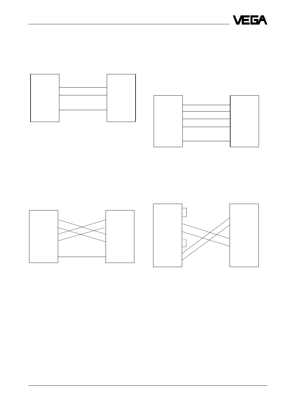
CP 524
+24V 16
R+ 13
R- 14
GND 24
-24V 12
T+ 10
t- 19
GND 21
COM 557
z18 R+
d20 R-
d18 T+
z20 T-
CP 524
Rx 4
/Rx 11
Tx 2
/Tx 9
GND 8
COM 557
d30 Rx
d32 /Rx
z30 Tx
z32 /Tx
d28 GND
CP 524
Rx 4
/Rx 11
Tx 2
/Tx 9
GND 8
COM 557
d30 Rx
d32 /Rx
z30 Tx
z32 /Tx
d28 GND
DIL switch 1 on VEGACOM additional board:
SW 8: OFF; SW 7: ON; SW 6: OFF.
Addressing of the process signals
CP 524
RxD 3
TxD 2
GND 7
COM 557
d18 RxD
z18 TxD
d16 GND
DIL switch 1 on VEGACOM additional board:
SW 8: ON; SW 7: OFF; SW 6: OFF.
Activate the RS 232 interface with the hook
switch on the additional board.
RS 422 (module RS422/485)
The mode full duplex
full duplex
full duplex
full duplex
full duplex must be set on the
RS 422/485 module.
V24 module
The factory setting of the 8 bridges is 1 - 2,
except bridge Br4 (2 - 3).
RS 485 (module RS422/485)
The mode half duplex must be set on the
RS 422/485 module.
Note:
Note:
Note:
Note:
Note:
On CP 524 only with special driver possible!
DIL switch 1 on VEGACOM additional board:
SW 8: OFF; SW 7: ON; SW 6: OFF.
TTY module
DIL switch 1 on VEGACOM additional board:
SW 8: OFF; SW 7: OFF; SW 6: ON.
Activate the TTY interface with the hook
switch on the additional board.