Installation guide, Operation, Product diagram – Veris Industries H8163-CB Install User Manual
Page 2: Data output specifications, H8163-cb
Z202879-0D
PAGE 2
©2012 Veris Industries USA 800.354.8556 or +1.503.598.4564 / [email protected]
03122
Alta Labs, Enercept, Enspector, Hawkeye, Trustat, Veris, and the Veris ‘V’ logo are trademarks or registered trademarks of Veris Industries, L.L.C. in the USA and/or other countries.
TM
H8163-CB
INSTALLATION GUIDE
OPERATION
The H8163-CB energy meter communication board is an optional field-installable
board for the H8163 energy meter that allows Modbus RTU communication. The
H8163-CB also enables the energy meter to provide true kW & kVAR demand
information.
The easy-to-install H8163-CB provides a simple, cost-effective way to network the
H8163 energy meter on a Modbus network.
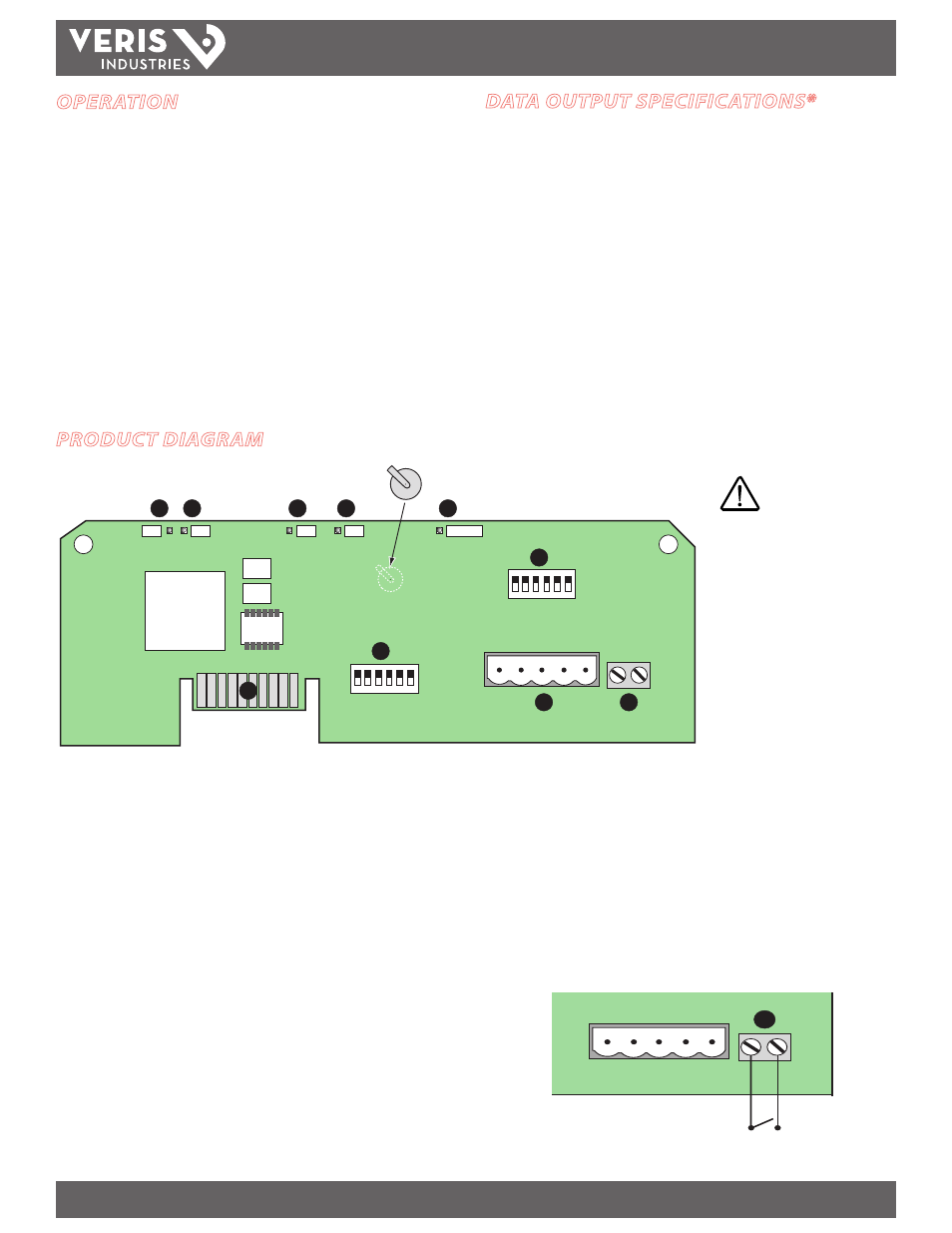
PRODUCT DIAGRAM
ON
1 2 3 4 5 6
ON
1 2 3 4 5 6
1
2
TX
RX
3
RX
4
TX
5
6
7
8
9
10
ALIVE
LITHIUM BATTERY
10
1.
RS-485 LED (TX):
Red LED; blinks to indicate data transmission from the H8163-
CB to the master.
2.
RS-485 LED (RX):
Red LED; blinks to indicate data reception from the master to
the H8163-CB.
3.
LED from Main Board (RX):
Green LED; blinks to indicate data reception from
the main board.
4.
LED from Main Board (TX):
Green LED; blinks to indicate data transmission to
the main board.
5.
ALIVE LED:
Green LED; should blink once per second to indicate normal operation.
6.
Network Address DIP Switches:
Use these DIP switches to set the network
address for the H8163-CB. See the Settings table on page 3 for more information.
7.
Connection to Energy Meter:
Install the H8163-CB in the energy meter by
inserting this connector into the connection slot at the top of the energy meter.
8.
Communication DIP Switches:
Use these DIP switches to set the H8163-CB
wiring type, baud rate, and parity. See “Setting the Communication DIP Switches”
on page 3 for instructions.
9.
RS-485 Communication Terminals:
Insert the RS-485 connector into these
terminals. See Wiring Diagrams on page 4 for instructions on wiring the connector
for 2-wire or 4-wire communications.
10.
Input Connector:
Use this terminal as the input connector for “end of demand
interval” signal from the utility or other source. Use an interposing isolated relay
as the dry contact for this terminal, as pictured below.
CAUTION! Danger of
explosion if battery is
incorrectly replaced.
Replace only with the same
or equivalent type. Dispose
of used batteries according
to applicable environmental
laws.
kWh, Consumption
kW, Real power
kVAR, Reactive power
kVA, Apparent power
Power factor
Voltage, line to line
Voltage, line to neutral
Amps, Average current
kW, Real Power ØA
kW, Real Power ØB
kW, Real Power ØC
Power factor ØA
Power factor ØB
Power factor ØC
Voltage, ØA to ØB
Voltage, ØB to ØC
Voltage, ØA to ØC
Voltage, ØA to Neutral
Voltage, ØB to Neutral
Voltage, ØC to Neutral
Amps, Current ØA
Amps, Current ØB
Amps, Current ØC
kW, Demand
kVAR, Demand
kW, Peak Demand
kVAR, Peak Demand
DATA OUTPUT SPECIFICATIONS*
* See the Modbus Point Map on www.veris.com for a full list of data input/output features.