Veris Industries Badger 3000 SERIES Install User Manual
Page 5
5
to their original states. If the Latch has been set to “ON”
once the set-point and set-delay have been satisfied the
relay will not release until manually reset.
Low Flow Set-Point
The Set-Point
“SETPT” must be a value less than the
Release Point
“RELP.”
The Relay output will have continuity between its “N.C”.
terminal and “COM” until the flow has dropped below
the Set-Point
“SETPT” for a continuous period of time
exceeding the Set-Point-Delay
“SDLY”, at which time
the N.C. connection will open, and the N.O. contact will
have continuity to the “COM” terminal. When the flow
has again risen above the Release Point
“RELP” for
a continuous period of time exceeding the
“RDLY” the
relay states will return to their original states. If the Latch
has been set to “ON” once the set point and set-delay
have been satisfied the relay will not release until manu-
ally reset.
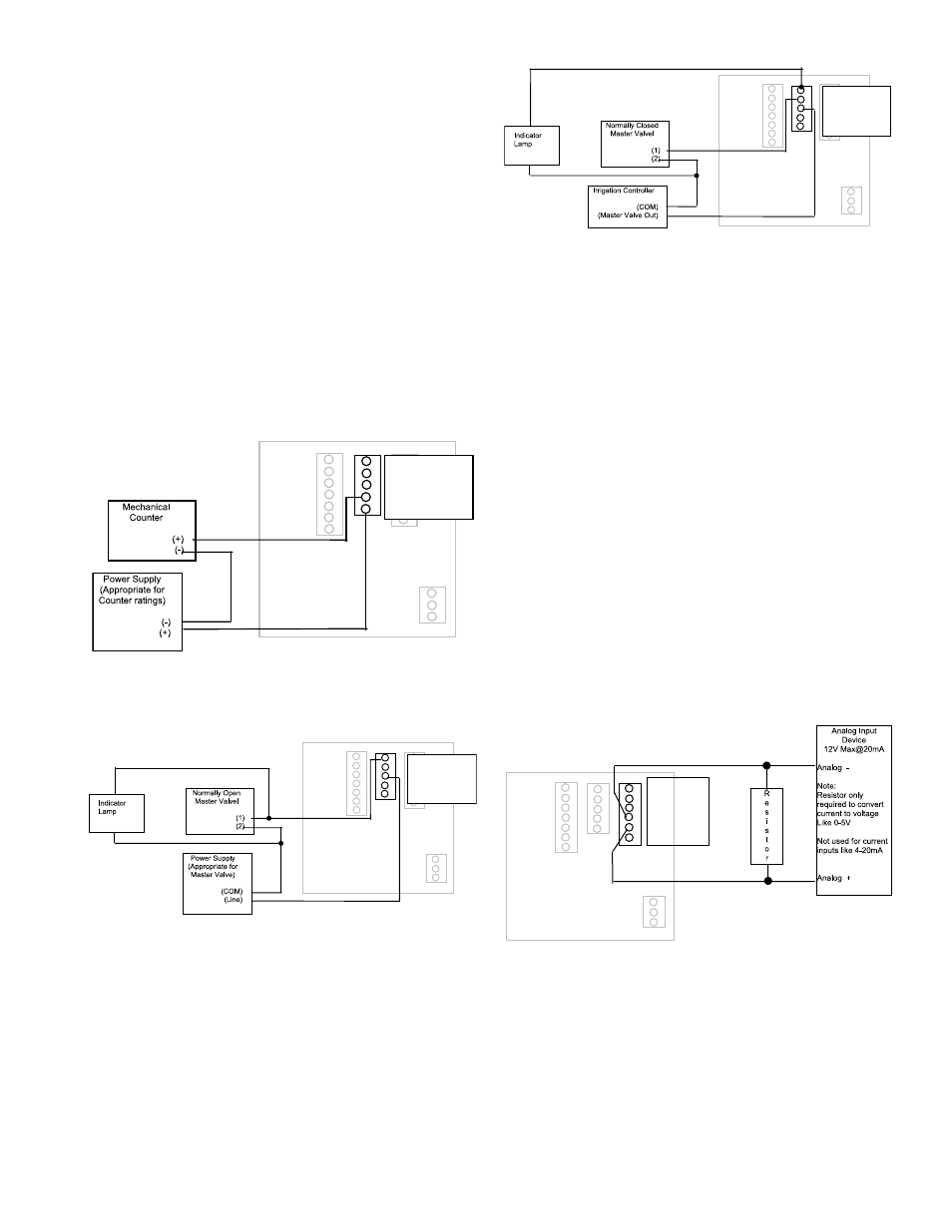
Figure 7: Relay and Switch Wiring Examples
1 RELAY 1 NO
2 RELAY 1 NC
3 RELAY 1 COM
4 PULSE 1 OUT
5 PULSE 2 OUT
Figure 8: Relay and Switch Wiring
Examples (continued)
High Flow Shut-Down with Normally Open Master
Valve with indication
1 RELAY 1 NO
2 RELAY 1 NC
3 RELAY 1 COM
4 PULSE 1 OUT
5 PULSE 2 OUT
Figure 9: Relay and Switch Wiring
Examples (continued)
High Flow Shut-Down with Irrigation Clock Normally
Closed Master Valve with indication Program as High
Flow with Latch
1 RELAY 1 NO
2 RELAY 1 NC
3 RELAY 1 COM
4 PULSE 1 OUT
5 PULSE 2 OUT
OUTPUT OPTION CARD:
If the Badger
®
Data Industrial
®
Model 3000 was ordered
with the Output Option card, it will have several additional
outputs.
These include the following:
1. Analog Output ( 0-20mA; or 4-20mA ) which can be
converted externally to 0-5VDC, 1-5VDC with a
250 Ohm resistor; or, 0-10VDC or 2-10VDC with a
500 Ohm resistor.
A 15VDC Power Supply is provided to permit current
sinking or sourcing
The Series 3000 has special software that permits
the Analog output.
2. USB for direct access to a computer using a standard
Mini-USB cable
3. RS-485 for fully addressable ModBus, or BACnet
communication.
Figure 10: Current Sourcing Analog Output
1 RS485 B
2 RS485 A
3 RS485 GND
4 LOOP +
5 LOOP -
6 GND