Veris Industries Badger 3000 SERIES Install User Manual
Page 4
4
Analog Input
As an alternative to the Pulse Inputs the Series 3000
can accept a Analog input. The input is non-isolated, but
can accept 0-1VDC; 0-5VDC; 0-10VDC; 0-20mA; and
4-20mA with both factory defined, and custom units of
measure.
Low impedance 100 Ohm input for current inputs optimiz-
es performance and flexibility or loop power supplies.
Both the Low and High end scaling are independent, and
field configured by the installer.
See Programming Flow Chart for required input con-
figuration
Analog Input Wiring
Solid State Switch and Form “C” Output Wiring
The Badger
®
Data Industrial
®
Series 3000 has one Nor-
mally Open (N.O.) solid state switch, and one Solid State
Form “C” Relay.
Check the specifications page for maximum voltage and
current ratings for each type output.
These outputs are completely independent, electrically
isolated, and can be programmed as either Pulse, or Set-
point outputs.
When the function “Totalizer” is selected the unit of mea-
sure and resolution are independent from the displayed
units, and can be programmed where 1 pulse occurs
once every 0000000.1 to 999999999.of units selected,
with any pulse width from 0001 to 9999mS.
When the “Alarm” is selected as the unit of measure and
the resolution is independent from the displayed units, it
allows the unit to be programmed as either a High or Low
rate Set Point. Since the Set-point, Release Point, and
their associated time delays are fully independent this
output can be either a classical High Rate, or Low Rate
alarm depending on the settings selected. When design-
planning keep in mind that although both of these outputs
can be programmed as alarm points only the Relay pro-
vides both N.O. and N.C. contacts. The switch is a simple
N.O. contact.
Examples:
High Flow Set-Point
The Set-Point
“SETPT” must be a value greater than
the Release Point
“RELP.”
The Relay output will have continuity between its “N.C”.
terminal and “COM” until the flow has exceeded the Set-
Point
“SETPT” for a continuous period of time exceeding
the Set-Point-Delay
“SDLY”, at which time the N.C. con-
nection will open, and the N.O. contact will have continu-
ity to the “COM” terminal. When the flow has dropped
below the Release Point
“RELP” for a continuous period
of time exceeding the
“RDLY” the relay states will return
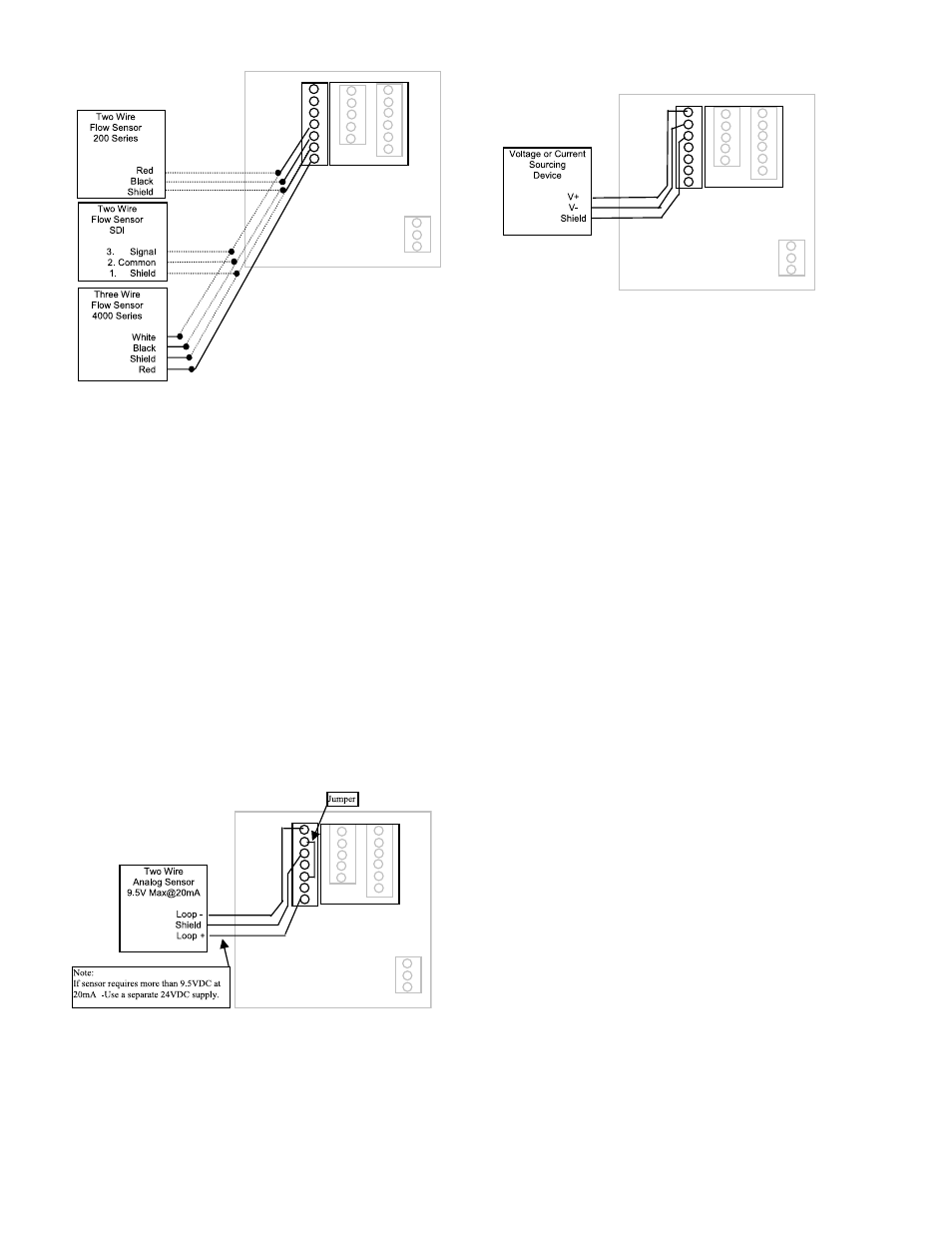
1 ANALOG IN+
2 ANALOG IN-
3 SHIELD
4 SENSOR IN
5 GND
6 SHIELD
7 SENSOR PWR
Figure 4: Data Industrial Flow Sensor
Wiring Examples
(Two and Three Wire Pulse Types)
1 ANALOG IN+
2 ANALOG IN-
3 SHIELD
4 SENSOR IN
5 GND
6 SHIELD
7 SENSOR PWR
Figure 5: 4-20mA Analog Loop Powered Wiring
Figure 6: Voltage or Current Sourcing Analog Inputs
1 ANALOG IN+
2 ANALOG IN-
3 SHIELD
4 SENSOR IN
5 GND
6 SHIELD
7 SENSOR PWR