Veris Industries Badger 3000 SERIES Install User Manual
Page 3
3
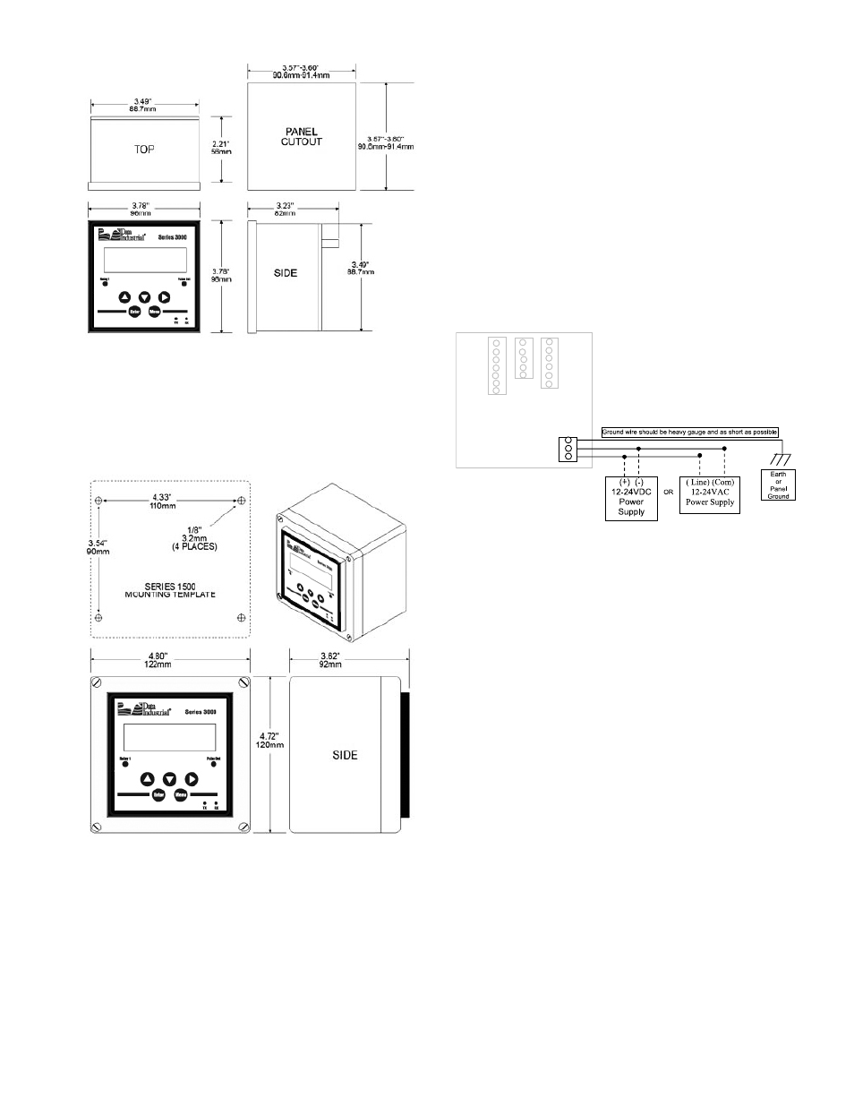
Wall Mount Installation
The Badger® Data Industrial® Model 3000 Wall Mount is
designed to mount onto a wall with four bolts or screws.
The mounting hole pattern and box dimensions for the
Model 3000 NEMA4 waII mount are shown in Figure 2.
ELECTRICAL INSTALLATION:
Power Supply Wiring
The Series 3000 requires 12-24 VDC/VAC to operate.
Check the specifications page for DC current draw, and
AC Volt-Amp requirements.
A fused circuit is always recommended.
Connect the positive of the power supply to the Series
3000 terminal marked (ACL/DC+), and connect the
negative of the power supply to the Series 3000 terminal
marked (ACC/DC-).
If a Badger Data Industrial plug-in power supply (Model
A1026, A-503) is being used connect the black-white wire
to the terminal marked (ACL/DC+) and the Black wire to
the terminal marked (ACC/DC-).
Figure 1: Panel Mounting Dimensions
Figure 2: Wall Mounting Dimensions
Earth
3
LV AC/DC(-) 2
LV AC/DC(+) 1
POWER
Figure 3: (Power Supply Wiring)
Flow Sensor Wiring
The Series 3000 Flow Sensor Inputs are extremely
versatile, designed to accept either two wire or three wire
pulse inputs (Badger Data Industrial 200 Series, 4000
Series), zero crossing sine wave inputs, or Analog inputs.
Although different rear panel terminals are used, all
parameters are set with the LCD/keypad interface. There
are no internal or external jumpers, switches, or potenti-
ometers to move or adjust.
Four types of Pulse Input Types are accommodated.
1. Pulse-DI: Used for all Badger Data Industrial Flow
Sensors.
Provides an internal Pull-Up resistor and uses “K” and
“Offset” values for calibration.
2. Pulse –K Factor:
Accepts non Zero Crossing inputs but provides no
internal pull-up, classical “K” ( Pulses/Gal) values for
calibration.
3. Pullup-K Factor:
Provides an internal Pull-Up resistor and uses
classical “K” ( Pulses/Gal) values for calibration.
4. Sine-K Factor:
Accepts Zero Crossing low voltage sourcing devices,
with classical “K” ( Pulses/Gal) calibration.
All the above wire the same as shown in Figure 4.
See Programming Flow Chart for required input con-
figuration.