Installation guide, Troubleshooting, Installing the cb in the h8163 energy meter – Veris Industries H8126-CB Install User Manual
Page 5: Veris industries, H8126-cb
VERIS INDUSTRIES
™
H8126-CB
INSTALLATION GUIDE
Z203167-0A
PAGE 5
©2009 Veris Industries USA 800.354.8556 or +1(0)503.598.4564 / [email protected]
10092
Alta Labs, Enercept, Enspector, Hawkeye, Trustat, Veris, and the Veris ‘V’ logo are trademarks or registered trademarks of Veris Industries, L.L.C. in the USA and/or other countries.
Complete the Communications Setup and Wiring instructions before
installing the board inside the meter.
The H8126-CB is designed as a plug-and-play accessory for the H8163 energy meter.
Follow these instructions to install the H8126-CB into the energy meter.
Turn off all power to the energy meter and the equipment in which it is installed.
1.
a. Remove the voltage terminal from the energy meter and all fuses.
b. Always use a properly rated voltage sensing device to confirm that power
is off.
To discharge static, follow the instructions that come with your anti-static or
2.
grounding strap.
NOTE: We recommend using an anti-static or grounding strap until you have
completed installation of the H8126-CB.
Slide the H8126-CB into the slot in the energy meter. The sides of the H8126-
3.
CB slide down into the channels on either side of the energy meter. When the
male connection to the energy meter clicks into place, the H8126-CB is properly
installed.
Insert the communication terminal onto the RS-485 communication terminals.
4.
If the demand subinterval feature is used, wire into the end of demand subinterval
5.
terminal.
Replace the voltage terminal into the energy meter.
6.
SLOTS
TOP
COMMS BOARD
BATTERY
CONNECTORS
CONNECTION
SLOTS
Observe handling precautions for static sensitive
devices to avoid damage to the circuitry which
would not be covered under the factory warranty.
ON
1 2 3 4 5 6
ON
1 2 3 4 5 6
1
2
TX
RX
3
RX
4
TX
5
6
7
8
9
10
ALIVE
D5
D6
D13
D14
D1
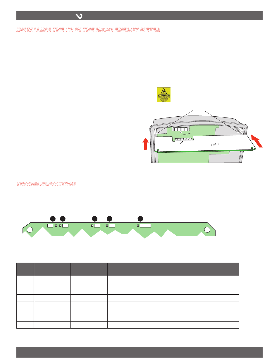
troubleshootIng
If communications are not working properly, first check that the board is properly
seated in its slot in the energy meter, and that the connector has clicked into place in
the connection slot on the meter.
There are five LEDs that indicate various types of communication.
During normal operation, all five LEDs will blink regularly. When an error occurs, the
abnormal LED will help determine where that error is.
LED
Number
LED Description
Abnormal Operation
Solution
1
RS-485 (TX)
Not blinking
No communication from the H8163 to the master.
· Check the wiring; N2- and N2+ may be reversed. Correct the wiring.
· If RX is blinking, verify the DIP switch address, parity, baud rate, and wire type.
2
RS-485 (RX)
Not blinking
No communication from the master. N2- and N2+ may be reversed. Correct the wiring.
3
From main board (RX)
Not blinking
Main board not responding. Contact customer support for assistance.
4
From main board (TX)
Not blinking but
“Alive” LED is blinking
Internal communications board error. Contact customer support for assistance.
5
“Alive” status
Steadily lit
Internal communications board error. Contact customer support for assistance.
InstallIng the cb In the h8163 energy meter