Installation guide, Installation, Rs-485 communications setup – Veris Industries H8126-CB Install User Manual
Page 3
VERIS INDUSTRIES
™
H8126-CB
INSTALLATION GUIDE
Z203167-0A
PAGE 3
©2009 Veris Industries USA 800.354.8556 or +1(0)503.598.4564 / [email protected]
10092
Alta Labs, Enercept, Enspector, Hawkeye, Trustat, Veris, and the Veris ‘V’ logo are trademarks or registered trademarks of Veris Industries, L.L.C. in the USA and/or other countries.
InstallatIon
This section describes the communications settings you must make to the H8126-CB.
When daisy-chaining N2 devices, follow these guidelines:
Connect up to 63 H8126-CB devices on a single daisy chain.
•
Each H8126-CB device on the daisy chain must have a unique address.
•
Before connecting the H8126-CB to the RS-485 communication wires,
set the address according to directions on this page.
For RS-485 cables, use shielded, twisted-pair wire (Belden Cable 1120A or
•
equivalent).
Terminate the last device on the daisy chain. If the H8126-CB is the last
•
device in a daisy chain, terminate it to ensure reliable communication per
the RS-485 standard (120Ω nominal impedence).
Selecting The Network Address – DIP Switches
Use the Network Address DIP switches to select the network address. Each H8126-CB
on a daisy chain must have a unique network address (from 1 to 63). Devices with the
same address will be unable to communicate.
Always set the address before you install the H8126-CB in the energy meter and
before you connect the energy meter to the daisy chain.
Each of the six DIP switches has a unique address value. The N2 Addressing section on
page 6 lists DIP switch positions for specific addresses.
Network Address DIP Switch Values
Switch
Value
1
1
2
2
3
4
4
8
5
16
6
32
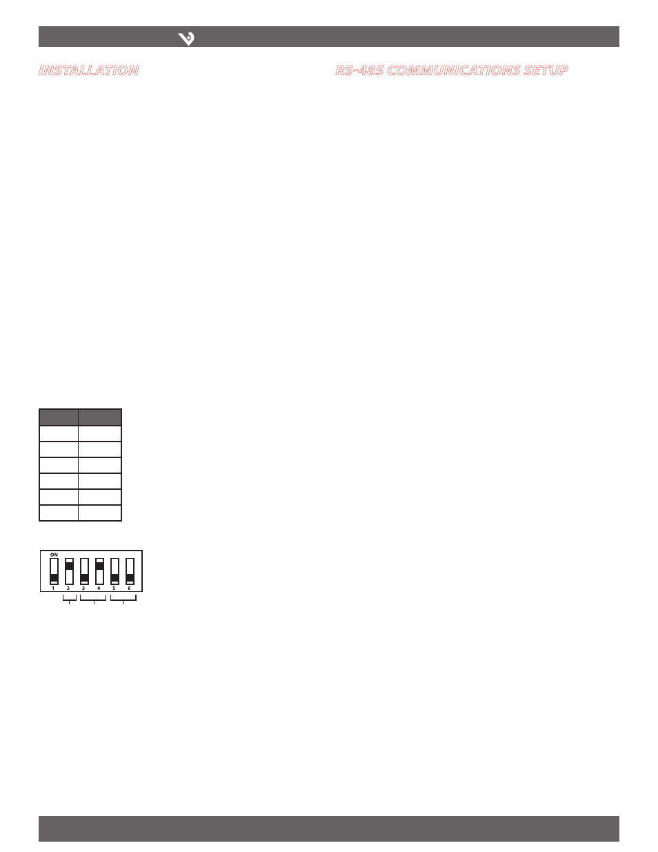
Setting the Communication DIP Switches
The wiring type, baud rate, and parity-
communication DIP switches are factory set to
N2 specifications (9600 baud, no parity, 2-wire
communication).
Wiring Baud
Parity
rs-485 communIcatIons setuP
Wiring the Connector
Remove the 5-pin connector from the RS-485 communication terminals of the
1.
H8126-CB.
Wire the communications connector as shown on page 4 (2-wire communication).
2.
Use a small, flat-blade screwdriver to tighten the connector screws.
3.
Replace the connector on the RS-485 communication terminals of the H8126-CB.
4.
If the H8126-CB is the last device in a daisy chain, terminate it to ensure reliable
5.
communication per the RS-485 standard (120Ω nominal impedence).